Widebody RCR40

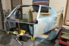
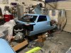
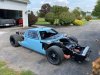
Been trying to make the best of the quarantine by dedicating some more time to the car. I have a goal of starting to spray some body panels the week of 5/11.

As an aside, the prevailing reason I chose a GT40 as a project was the rarity (even as a replica). I attend many car shows and cruises and have only seen -1- mk2 superformance in all my travels. I wondered, with all the Cobra's out there, how there weren't more 40's. I know the answer now. I believe I could have built 4 nice cobras with the time and money I have thus far. I'm not complaining about the path but after 4 1/2 years I tend to get a little philosophical and retrospective.

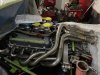
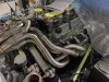
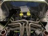
Anyway, some highlights.

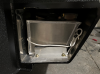
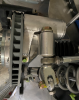
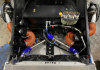
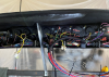
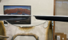
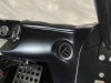
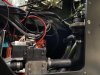
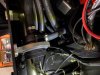
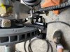
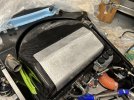
- radiator and AC installed
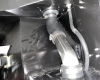
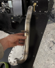
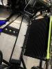
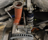
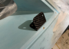
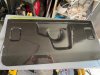
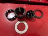
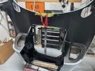
- Front and rear brake ducts
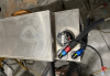
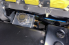
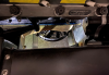
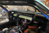
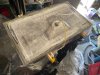
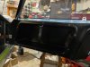
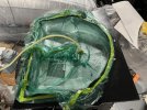
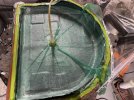
- fuel tanks installed
 

Attachments

  • Tank 1.PNG
    Tank 1.PNG
    2 MB · Views: 985
  • Tank 2.PNG
    Tank 2.PNG
    1.7 MB · Views: 877
  • Fuel hose.PNG
    Fuel hose.PNG
    2 MB · Views: 734
  • Coolant hose 1.PNG
    Coolant hose 1.PNG
    1.1 MB · Views: 756
  • Coolant hose.PNG
    Coolant hose.PNG
    1.2 MB · Views: 749
  • AC rad.PNG
    AC rad.PNG
    1.2 MB · Views: 774
  • Rad area.PNG
    Rad area.PNG
    2 MB · Views: 845
Some more picts. I also crammed a Canton coolant bottle down next to the engine. Was about the only place it would fit. I had to cut the top leading edge to clear the block.
 

Attachments

  • Front brake duct.PNG
    Front brake duct.PNG
    2.3 MB · Views: 829
  • Rear brake duct.PNG
    Rear brake duct.PNG
    1.2 MB · Views: 796
  • Front hose.PNG
    Front hose.PNG
    1.9 MB · Views: 816
  • Rear hose.PNG
    Rear hose.PNG
    2 MB · Views: 770
  • Coolant bottle.PNG
    Coolant bottle.PNG
    2 MB · Views: 814
  • Rad area 2.PNG
    Rad area 2.PNG
    2.1 MB · Views: 872
Other people have talked about the engine bay heating issues especially when the car is idling. Some have put fans in the round cutouts near the top radius rod mounts. I didn't have a fan size that I felt would move the volume required to keep the engine bay temps down. Also, aesthetically, I wanted to move the fan lower and (mostly) out of sight.

I cut up 2 pieces of 1.25"X .063" angle aluminum to bridge the engine opening in the chassis. I used a single Spal 9" low profile puller fan. It's rated at just over 700 cfm. It also turns my car into a Chaparral fan car. #maxsuckage.
 

Attachments

  • Under fan.PNG
    Under fan.PNG
    1.6 MB · Views: 852
I've been negligent in posting progress so I've got several months of progress. I'll have to say the wiring, in an effort to make it modular and logical, has been difficult. I was hoping to just wing it but ended up having to design something from the ground up. I used cylindrical connectors so the dash can be detached from the chassis and breaker panel portion. During this part of the project I questioned my sanity. The supplied 13 circuit fuse box would have probably worked OK. In my infinite wisdom, no, I'll design my own wiring.
 

Attachments

  • dash wiring.PNG
    dash wiring.PNG
    2.2 MB · Views: 690
  • dash in car.PNG
    dash in car.PNG
    2.2 MB · Views: 727
Bodywork, bodywork, bodywork. Perhaps I've said this before but the fiberglass need considerable work to make it decent. I have no reference what fiberglass replica is better than others. If there are suppliers that are considerably worse than this -well- let god have mercy on your soul. So many little inclusions, voids, surface irregularities, etc.

I built a fixture to hang the doors for finish prep and painting. Perhaps total luck, but the alignment of the doors turned out better than expected. When closed together the doors align with 1/64". I don't think I can do any better.

I'm using those carbon SPA side mirrors and thought if I mount them directly to the plexi there is no doubt it would break. I molded a couple little carbon brackets to mount behind the side windows to anchor the mirror to door body.
 

Attachments

  • doors.PNG
    doors.PNG
    2.2 MB · Views: 740
  • door alignment.PNG
    door alignment.PNG
    1.7 MB · Views: 710
  • mirror bracket.PNG
    mirror bracket.PNG
    1.8 MB · Views: 786

Randy V

Moderator-Admin
Staff member
Admin
Lifetime Supporter
They are rough, but then I am told all of the originals were rough as well since they were made as racing cars from clay and plaster bucks... I had many months (part time) of work on mine to get it up to scratch..
 
What a year it's been. I feel like the trajectory of humanity has changed. For another day I suppose.

I have used some of the quarantine time to work on the car. Headers and paint are 2 that I've been contemplating for some time. I didn't get the whole car painted as I believe there will be a bit more trimming and fitting on the front and rear clamshells that can be done once the car is running and driving.

The paint color is the Porsche gulf blue which seems a little more gray than the original. I got the base from sherwin williams and clear is the unversal clear from SPI. The clear sprays really nice. I've painted with PPG omni previously and though this was much better. I'm not a painter, but the SPI favors my abilities.

As best I can describe, making headers for this car are like wrangling order from pure chaos. It's my first set of headers and rather complex set at that. I couldn't contrive a way to build them other than directly on the car then put them on some type final weld fixture for finishing. Another issue I need to contend with is the sealing the individual tubes to the collector. I have about a .035 difference between the ID of the collector tubes and the OD of the pipes. I'm thinking of either making copper gaskets that insert or stretching some 1.75 OD tubing the proper amount to take up the difference. Suggestions welcome here.
 

Attachments

  • paint.jpg
    paint.jpg
    532.6 KB · Views: 692
  • driver header.jpg
    driver header.jpg
    443.1 KB · Views: 696
  • IMG_1283.jpg
    IMG_1283.jpg
    427.1 KB · Views: 665
  • IMG_1282.jpg
    IMG_1282.jpg
    426.2 KB · Views: 679
Need some help!!!

I think I'm going to set my own windshield using urethane. I can't seem to find anyone that'll do the job. Are there others who have set theirs on a RCR40? I bought some gasket material that is typically used on the SPF GT's to surround the glass edge. Some questions:

- Do I use some dam material to keep the urethane in? What size?
- Does the SPF gasket set the spacing or are shims needed?
- What urethane package (glue and primer) do people recommend?
- Any tricks you can suggest?
 

Chris Kouba

Supporter
I didn't use any trim, and word has it, the originals didn't either. I did not verify.

I used an adhesive but didn't gap fill with it as it isn't UV stable. The adhesive was applied so it'd be under the black border of the screen, so it'd be out of direct sunlight. It's been a while but I believe I just used a black RTV (and UV stable) silicone to fill the gap when it was cured.

I just smoothed things out after applying the silicone and it's been issue free for ~7000 miles.

I will look for what I used for the adhesive. It was recommended by someone from the forum, but I can't remember what it was or who pointed me that direction.
 

Ian Clark

Supporter
Hi Adam,

Very nice work on the car, looking back through your postings shows it.

About the color, the Gulf "Powder Blue" reacts to different light sources - indoor florescent, incandescent, led and also outside on a cloudy vs sunny day. At dusk on a clear evening the color actually appears to glow for a few minutes.

We came to find out, on a complete respray of a CAV GT40, there's quite a bit of clear in the paint formula even though it's a solid non metallic color. So the light travels through the paint affecting what you see. So don't prejudge the paint yet.

Also because of the paints translucence be sure to maintain the same color of primer under the paint for the other panels to ensure proper paint match. This is super important.

Not surprising to find regular glass shops reluctant to touch the car. If you want to tackle it yourself find a good professional bodyshop supply house. They will have in stock the correct primer for the bond area, fresh urethane sealer and other supplies you will need (like the push in and bonded edge molding). They might even know someone who will do the job for you.

We've had three windshields rebonded here, all different brand of GT40 replicas btw, so it has to be done right. The roof spider becomes much more rigid once the windshield is mounted. It becomes a structural part of the car.

Cheers
Ian
 
I went to a local car glass company and asked them if they where willing to place my windscreen on site and they where.
It cost me €121,- and they did a perfect job. Primer first then the special glue.
No trim also and as the spider is not perfect equal on both sides they had to figur a way between to make it sit perfect which they did.

My 50cents, don't try it yourself, it would make a mess in wich you'r not satisfiet with.
 
The road has been rough but I'm still pushing on with this car. Sometimes I think I let this project get out of hand. Perhaps its too easy to talk yourself into refining the nuanced details. I wanted to use this project to expand my capabilities in paint, molding, wiring, and fabrication, which it has. The "challenge yourself" and the "get it done" parts are in constant conflict. So far, "just get it done" is in a distant 2nd place.

- I added an inline coolant pump in case I have flow issues when the car is up and going. It's the Bosch unit that used in many automotive applications (pn 0392023004). Some people reported that the pressure differential isn't sufficient to get flow. Something I don't want to realize after the whole system is together. I hung it in the passenger footwell area just inside the hatch panel.

- Here's an example of unnecessary stuff. I didn't like the vent offerings. I had Miata pieces that were cut up and didn't like the fit or appearance. So I decided to design and print my own parts. The parts were printed using SLS from 40% fill PA12 material. They aren't a deep black but match the dash well enough.

- Firewall... I started working on the RCR supplied piece (1/8" aluminum) and wasn't liking the result. Any welding on it made it warp and the idea of bolting on a kickout for the water pump didn't appeal to me. So, what's the answer... mold another part...
 

Attachments

  • vacuum firewall.jpg
    vacuum firewall.jpg
    107.4 KB · Views: 273
  • finished firewall.jpg
    finished firewall.jpg
    104 KB · Views: 288
  • vent in.jpg
    vent in.jpg
    62.8 KB · Views: 288
  • vent parts.jpg
    vent parts.jpg
    67.2 KB · Views: 276
  • coolant pump 2.jpg
    coolant pump 2.jpg
    94.7 KB · Views: 289
  • coolant pump 1.jpg
    coolant pump 1.jpg
    89.9 KB · Views: 297
Finishing the doors and interior:

The door boxes turned into a much larger project than anticipated. The gelcoat was terrible. Tons of thin area air pockets that popped when I ran my finger over them and so many cracks from being pried from the mold. Didn't realize how much bodywork time it was going to require. I designed and printed (again in 40% fill PA12) some door pulls for the back of the box and attached some Sabelt nylon straps also. I found that unless you slam the doors a solid handhold is needed to pull them fully closed against the gaskets.

The side windows went in without too many issues. I used some neoprene adhesive backed gasket on the back to seal them up. I have little confidence it will provide a water tight seal.

Interior is also mostly done. Once I fully test the wiring the rats nest behind the breaker panel will be organized. I also added an aluminum kick plate for the passenger which should make the experience Cadillac comfortable.
 

Attachments

  • side window.jpg
    side window.jpg
    76.3 KB · Views: 300
  • door card 2.jpg
    door card 2.jpg
    70.7 KB · Views: 298
  • door card 1.jpg
    door card 1.jpg
    85.3 KB · Views: 294
  • interior.jpg
    interior.jpg
    78.6 KB · Views: 354
And the march goes on. Last weekend I had a goal of final testing the electrical system, bleeding the brakes and clutch, adding coolant, and putting the wheels on for a photo op. I got as far as the rear wheels when I noticed the parking brake wouldn't clear the inside barrel of the rim. I don't know how this was missed but it appears the RCR parking brake bracket was too tall (radially) for the 15" wheels. Maybe it was a SL-C bracket, I don't know. I ended up making a fixture because the position and spacing is pretty important. Then cut and rewelded the bracket back together .300 closer to the rotor OD.

I know people talk about the height and overall size of the gt40's but it doesn't seem right in real life. My car has been in the garage and 18" in the air on stands for a long time. I lost perspective until it was pushed outside. I can step on the roof like a stepstool. Nutz.
 

Attachments

  • parking brake.jpg
    parking brake.jpg
    85.8 KB · Views: 327
  • roller 3.jpg
    roller 3.jpg
    128.6 KB · Views: 341
  • roller 2.jpg
    roller 2.jpg
    127.4 KB · Views: 346
  • roller 1.jpg
    roller 1.jpg
    116.6 KB · Views: 317
Adam, that firewall is gorgeous! I was juts talking to the engine builder today about the lack of room. The bulge would help!
How does one get a mold of that???
 
Adam, that firewall is gorgeous! I was juts talking to the engine builder today about the lack of room. The bulge would help!
How does one get a mold of that???


I have the original mold that the part was pulled from but I made some other changes after. I intend to pull a new mold from the current part at some point. That wasn't the easiest part to make. Between all the junk on the engine front and my seats tucking really close to the water pump it was a process.
 

Markus

SPRF40
Lifetime Supporter
Adam,
Just searching for something and stumbled over your built thread (again).
Any Updates?

Regards
Markus
 
Back
Top