I had troubles with 5th and reverse as well. What I found is the bolt attaching the heim joint on the shift cable was stricking the transaxle case. You probably need to reverse the bolt so that the nut side is against the case and cut the bolt as short as it will go.

You are using an out of date browser. It may not display this or other websites correctly.
You should upgrade or use an alternative browser.
You should upgrade or use an alternative browser.
Chuck and Ryan's RCR Build
- Thread starter CESLAW
- Start date
Jonathan:
Thanks for the tip. I will check that out.
How did you route your shift cables?
Does your tranny have the reverse detent? When I unscrewed the detent I found that the spring and ball that should have been inside were missing. I am trying to figure out whether it will go into reverse and fifth gear without it and if its sole function is to prevent an inadvertant shift from 5th to reverse.
Chuck
I routed both cables on the right side of the motor (looking forward). You need to be careful to put the cables where the AC compressor will not hit them. I routed it under the suspension cross brace. I attached it to the side of the frame with padded P shaped hose hangers and zip tied it to the link for the rear clip so that they would not hit the axles. I went down this side of the engine to leave the other side for an oil filter relocator.
Mine does have a detent. I was missing one detent but I managed to get one. I don't remember which gear it was for. It was tough to find. Audi does not sell it and the wreakers don't want to sell them. They are only interested in selling a complete transaxle.
You should still be able to shift without it for testing. You may need to pull the inspection cover to make sure all the gates are in nuetral. I have PMed my phone number to you if you want to talk about it some more.
That is the detent that I was missing. I was still able to cycle through all the gears.
The Cover Up
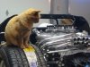
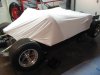
The idea of cat paw prints on the freshly painted dash board or cat hair on the leather seats was more disconcerting than sitting through the presidential primary debates. A cover for the chassis while the car was under construction was needed. When Target had their January bed sheet sale a possible solution came to mind. As it turns out a fitted king size bed sheet makes an ideal cover for most of the chassis keeping dust – and the cat – off. The top sheet and the pillow cases are a bonus. The soft, 100% cotton won’t hurt anything. And they are cheap. The solution to the primary debates dilemma? The Speed Channel!
The idea of cat paw prints on the freshly painted dash board or cat hair on the leather seats was more disconcerting than sitting through the presidential primary debates. A cover for the chassis while the car was under construction was needed. When Target had their January bed sheet sale a possible solution came to mind. As it turns out a fitted king size bed sheet makes an ideal cover for most of the chassis keeping dust – and the cat – off. The top sheet and the pillow cases are a bonus. The soft, 100% cotton won’t hurt anything. And they are cheap. The solution to the primary debates dilemma? The Speed Channel!
Attachments
Clutch Slave Cylinder, Linkage
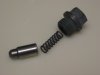
The new slave cylinder easily slid into place. A bit of anti seize will make future removal easier. The pin was hammered into place after we confirmed that the adjustment was appropriate.
The slave cylinder requires a sitting to match it to the -3AN clutch line. This is not a part you will find at your local NAPA or Autozone store. The fitting is a 12 mm to -3AN. We ordered it from Mesa Hose Inc., Costa Mesa, CA. Phone: 949-645-2661. Specify part Goodridge P/N 306-03-M121D / Sachs P/N SH1640.
Brake fluid was added to the reservoir and the line was bled. The slave cylinder is self adjusting, with a spring that keeps it engaged. After installing the cylinder and depressing the clutch pedal, we noted that it seemed to disengage the clutch in an appropriate manner with out any apparent need for further adjustment. It would seem that the parts supplied by Kennedy Engineered Products were designed to be compatible with the stock Audi slave cylinder without further adjustment. This was a pleasant surprise.
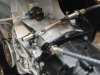
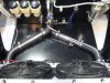
The shifter cables were installed utilizing the bracket and lever supplied by RCR. After trying several different options, we opted to simply run the two cables along the right side of the engine secured to the chassis, then beneath the right half - shaft, up and around to their respective brackets. A couple of clamps will be fabricated to assure the cables remain in place.
The shift mechanism was adjusted. The gear positions were quite evident making this task straightforward. Undoubtedly there will need to be some fine tuning of the shifter cables and, perhaps, the clutch, once the engine is fired up.
The new slave cylinder easily slid into place. A bit of anti seize will make future removal easier. The pin was hammered into place after we confirmed that the adjustment was appropriate.
The slave cylinder requires a sitting to match it to the -3AN clutch line. This is not a part you will find at your local NAPA or Autozone store. The fitting is a 12 mm to -3AN. We ordered it from Mesa Hose Inc., Costa Mesa, CA. Phone: 949-645-2661. Specify part Goodridge P/N 306-03-M121D / Sachs P/N SH1640.
Brake fluid was added to the reservoir and the line was bled. The slave cylinder is self adjusting, with a spring that keeps it engaged. After installing the cylinder and depressing the clutch pedal, we noted that it seemed to disengage the clutch in an appropriate manner with out any apparent need for further adjustment. It would seem that the parts supplied by Kennedy Engineered Products were designed to be compatible with the stock Audi slave cylinder without further adjustment. This was a pleasant surprise.
The shifter cables were installed utilizing the bracket and lever supplied by RCR. After trying several different options, we opted to simply run the two cables along the right side of the engine secured to the chassis, then beneath the right half - shaft, up and around to their respective brackets. A couple of clamps will be fabricated to assure the cables remain in place.
The shift mechanism was adjusted. The gear positions were quite evident making this task straightforward. Undoubtedly there will need to be some fine tuning of the shifter cables and, perhaps, the clutch, once the engine is fired up.
Attachments
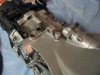
Thermostat Cover
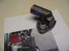
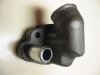
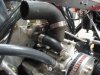
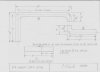
Finding a thermostat housing that would fit proved to be a real challenge. We finally settled on a generic cast iron housing (Stant 31418), cut out a notch and re welded it with a 30 degree backward angle. Below is a picture of the housing before the modification mounted on the engine with a straight edge demonstrating the clearance problem. A close up view after the end was cut off, welded, filed smooth and painted with ‘wrougnt iron’ engine paint is also included.
A 180 degree thermostat was used. A standard Ford 302 bypass hose was added.
The thermostat cover protrudes about a quarter of an inch inside the car, so a small ‘bubble’ will be added to the removable fire wall, similar to the bump to clear the pulley. A quarter inch section of the firewall frame was cut to clear the right angle hose coming from the thermostat cover. This arrangement is tight, but there is enough clearance to, hopefully, avoid any problems.
Attachments
Coolant Hoses, Part I
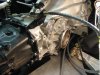
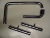
The output from the thermostat cover was routed to the starboard side of the engine and then down behind the alternator. The idea of running rubber hoses close to the exhaust manifold was not very appealing. A detailed diagram of the two sections of pipe needed for the coolant line was drawn up. While we were at it, we decided to also have stainless pipes fabricated for the front section, with connections for the heater hoses. The sections of stainless line were fabricated by Stainless Specialities http://www.stainless-specialties.com. (By the way, they fabricated the side pipes for our Cobra and did an exceptional job). John did an outstanding job. The shine on the pipes was mirror like and the bends were sharp and crisp. Stainless Specialties is an excellent resource for not only exhaust pipes but special projects like this.
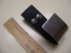
The long sections of stainless tubing needed support. Two brackets were fabricated from a seven inch length of 1 ½ aluminum stock bent in the shape of the letter “J.” Since the hose will move a bit with the motor, the stainless tubing was not anchored to the chassis but rather simply rests in the J brackets. A piece of rubber should prevent vibrations. The visible portion of the brackets was sanded with 1000 grit paper and then polished with Mother’s Billet polish, yielding a shine that rivaled the stainless tubing. One bracket is near the thermostat cover secured to the bulkhead and the second supports the lower most portion of the stainless tube secured to the chassis.
This plumbing arrangement required that the oil dip stick be replaced. Canton provides a dipstick for the oil pan ready to secure to an existing bung. It worked fine.
The output from the thermostat cover was routed to the starboard side of the engine and then down behind the alternator. The idea of running rubber hoses close to the exhaust manifold was not very appealing. A detailed diagram of the two sections of pipe needed for the coolant line was drawn up. While we were at it, we decided to also have stainless pipes fabricated for the front section, with connections for the heater hoses. The sections of stainless line were fabricated by Stainless Specialities http://www.stainless-specialties.com. (By the way, they fabricated the side pipes for our Cobra and did an exceptional job). John did an outstanding job. The shine on the pipes was mirror like and the bends were sharp and crisp. Stainless Specialties is an excellent resource for not only exhaust pipes but special projects like this.
The long sections of stainless tubing needed support. Two brackets were fabricated from a seven inch length of 1 ½ aluminum stock bent in the shape of the letter “J.” Since the hose will move a bit with the motor, the stainless tubing was not anchored to the chassis but rather simply rests in the J brackets. A piece of rubber should prevent vibrations. The visible portion of the brackets was sanded with 1000 grit paper and then polished with Mother’s Billet polish, yielding a shine that rivaled the stainless tubing. One bracket is near the thermostat cover secured to the bulkhead and the second supports the lower most portion of the stainless tube secured to the chassis.
This plumbing arrangement required that the oil dip stick be replaced. Canton provides a dipstick for the oil pan ready to secure to an existing bung. It worked fine.
Attachments
Have you worked out the issues with your shifter to get 5th and reverse?
You're doing an excellent job real craftmanship
It's looking great
Frank
It's looking great
Frank
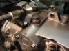
The problem with not being able to shift into fifth and reverse, which we thought was due to a missing detent, was actually an adjustment issue. That discovery was made when installation of a detent had no affect on the problem. A bit of adjustment of the cables and then the tranny slid into all gears regardless of whether the detent was in or out.
When installing the detent, we discovered that one does not simply crank it down. Doing so essentially locked up the shifter. A couple of washers on the detent housing took some pressure off the detent and now it works just fine. With the detent in place, one cannot shift directly from fifth to reverse; you need to go into neutral, a push to the left, then right and back into reverse, which hopefully is how it is supposed to work.
When installing the detent, we discovered that one does not simply crank it down. Doing so essentially locked up the shifter. A couple of washers on the detent housing took some pressure off the detent and now it works just fine. With the detent in place, one cannot shift directly from fifth to reverse; you need to go into neutral, a push to the left, then right and back into reverse, which hopefully is how it is supposed to work.
Attachments
Brakes
Only three points:
1. Carroll Smith would not be happy. We used Teflon tape on the brake line fittings secured to the calipers. But it was necessary so that a secure connection could be made with the right angle fitting pointed in the correct direction. It worked. No leaks.
2. Carroll Smith would not be happy. We used Russell’s anti seize and sealant on all of the threaded AN fittings. (Jegs, part # 67150, $11.99). It worked. No leaks.
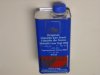
3. Brake fluid does not generate as much debate as engine oil, but it is probably not too far behind. At the risk of adding to the debate, our two cents worth follows. We opted to use ATE Typ 200. It is a DOT 4 fluid recommended by BMW and sold by such suppliers as Baviarian Autosport, www.BavAuto.com. ($11.95 for 1 liter, which is just enough for the brakes and clutch. But buy two, just in case). We selected it for several reasons. (1) It is German (we have two BMWs and one Porsche as our daily drivers). (2) It is DOT 4, fully compatible with the more common DOT 3. (It is NOT silicone; that would be DOT 5). (3) It has high dry and wet boiling points. (4) It comes in a metal can, extending the shelf life. (5) Here is the really neat part. It comes in two colors: either ATE 200, which is the color of Corona beer, or ATE Super Blue Racing which is, you guessed it, blue. (It is the same stuff, despite the different names). So when it comes time to change the brake fluid, use the alternate color. When bleeding the lines, you will know you added enough when the color changes. Cool. Carroll Smith would be VERY happy.
By the way, for those that have not been introduced, Carroll Smith is the author of several excellent books including Prepare to Win; Tune to Win; Drive to Win; Engineer to Win; and my personal favorite, Nuts, Bolts, Fasteners and Plumbing Handbook.
Only three points:
1. Carroll Smith would not be happy. We used Teflon tape on the brake line fittings secured to the calipers. But it was necessary so that a secure connection could be made with the right angle fitting pointed in the correct direction. It worked. No leaks.
2. Carroll Smith would not be happy. We used Russell’s anti seize and sealant on all of the threaded AN fittings. (Jegs, part # 67150, $11.99). It worked. No leaks.
3. Brake fluid does not generate as much debate as engine oil, but it is probably not too far behind. At the risk of adding to the debate, our two cents worth follows. We opted to use ATE Typ 200. It is a DOT 4 fluid recommended by BMW and sold by such suppliers as Baviarian Autosport, www.BavAuto.com. ($11.95 for 1 liter, which is just enough for the brakes and clutch. But buy two, just in case). We selected it for several reasons. (1) It is German (we have two BMWs and one Porsche as our daily drivers). (2) It is DOT 4, fully compatible with the more common DOT 3. (It is NOT silicone; that would be DOT 5). (3) It has high dry and wet boiling points. (4) It comes in a metal can, extending the shelf life. (5) Here is the really neat part. It comes in two colors: either ATE 200, which is the color of Corona beer, or ATE Super Blue Racing which is, you guessed it, blue. (It is the same stuff, despite the different names). So when it comes time to change the brake fluid, use the alternate color. When bleeding the lines, you will know you added enough when the color changes. Cool. Carroll Smith would be VERY happy.
By the way, for those that have not been introduced, Carroll Smith is the author of several excellent books including Prepare to Win; Tune to Win; Drive to Win; Engineer to Win; and my personal favorite, Nuts, Bolts, Fasteners and Plumbing Handbook.
Attachments
Coolant Hoses, Part II
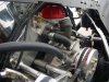
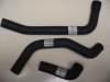
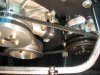
We found a hose that had a flared section which fit the lower intake on the water pump. (Part number D71281 from Advanced Auto Parts.) It is a tight fit between the lower pulley, AC compressor and compressor belt, but with careful adjustment the hose was centered about a half inch from each of these three obstacles. This hose was connected to a hose with an 80degree bend long enough to reach the aluminum coolant tube (Part number B70541CS from Advanced Auto Parts). The lower end of the stainless pipe from the thermostat cover was connected with two 45 degree sections cut from two additional hoses (Part number E-70755CS from Advanced Auto Parts. You might as well buy six, because you will need four for the front end of the car). A lot of cutting and fitting of hoses was needed to make all the necessary connections. Short sections of 1 ½” stainless were used to connect the hose pieces.
The front connections required four 45 degree sections. Four more hoses were used. (Part number E-70755CS from Advanced Auto Parts). The two straight stainless pipes were inserted, but the heater hoses will not be connected until later, once we are sure the coolant system is working properly. Note that one of the angled hoses on the driver side is cut a couple of inches longer due to the offset of the tunnel.
Attachments
Radiator, Part I
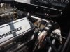
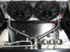
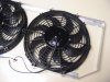
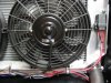
To secure the two fans, a bracket was fabricated from aluminum stock. Two sections of aluminum angle stock, 1” x 1”, were used for the top and bottom. The sides of the bracket were fabricated from 1 ¼” flat stock, bent so that they could be secured to the radiator brackets. A notch was cut out of the top section to make a proper fit. The top and bottom brackets were secured to the side brackets with rivets. The fans were secured to the bracket with metric bolts which had heads that fit perfectly into the mounting slots on the fan shrouds. The completed assembly was secured to the radiator through the same holes used to secure the radiator to the chassis. This permitted the fans to be securely mounted without placing any stress on the radiator itself.
The condenser was secured to the radiator using the supplied brackets, small button head screws and locking nuts. A thin piece of rubber was placed between the brackets and the radiator housing.
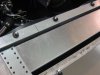
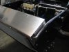
A cover plate was fabricated from eighth inch thick aluminum, which covers the radiator, condenser and ancillary tubing. It has a half inch lip on the leading edge. The same four bolts securing the top of the fan shrouds to the fan bracket extend up to secure the cover plate. The front of the cover plate is secured to the condenser with two screws, with a quarter inch rubber washer between the condenser and the cover plate, once again to provide for expansion. Nylon lock nuts were used, but not over tightened. This cover plate serves ties the assemblies together adding to the rigidity of the fan – radiator – condenser union. It hides the AC connections on the side from casual view. And it make the system look much ‘cleaner.’
A Painless water resistant fan relay was mounted on the right side of the fan bracket.
The wiring was completed. The fans and relay were grounded to the fan bracket, but a separate ground wire was also connected to this grounding screw to the dedicated chassis ground stud on the right lower side of the dash, referred to previously, just to make sure the ground was adequate.
We wired both fans together. We may change the wiring in the future so that one fan is activated by the engine temperature thermostat and trinary AC switch, and the other fan is manually operated by the dash switch. We have arranged the wiring so that this change can be easily made if deemed appropriate. Later the wiring will be wrapped with the Painless wire wrap.
One inch diameter, eighth inch thick, rubber washers were placed between the radiator brackets and the chassis to permit expansion. Two were used in most locations to provide a snug, but not too tight, fit without distorting the radiator mounting bracket. Nylon lock nuts were used with quarter inch bolts which were not over tightened to permit expansion. The front lower portion of the radiator was placed on thick rubber bushings as the radiator was installed to avoid direct contact with the chassis. Once the mounting brackets are snug, these washers could be removed.
To secure the two fans, a bracket was fabricated from aluminum stock. Two sections of aluminum angle stock, 1” x 1”, were used for the top and bottom. The sides of the bracket were fabricated from 1 ¼” flat stock, bent so that they could be secured to the radiator brackets. A notch was cut out of the top section to make a proper fit. The top and bottom brackets were secured to the side brackets with rivets. The fans were secured to the bracket with metric bolts which had heads that fit perfectly into the mounting slots on the fan shrouds. The completed assembly was secured to the radiator through the same holes used to secure the radiator to the chassis. This permitted the fans to be securely mounted without placing any stress on the radiator itself.
The condenser was secured to the radiator using the supplied brackets, small button head screws and locking nuts. A thin piece of rubber was placed between the brackets and the radiator housing.
A cover plate was fabricated from eighth inch thick aluminum, which covers the radiator, condenser and ancillary tubing. It has a half inch lip on the leading edge. The same four bolts securing the top of the fan shrouds to the fan bracket extend up to secure the cover plate. The front of the cover plate is secured to the condenser with two screws, with a quarter inch rubber washer between the condenser and the cover plate, once again to provide for expansion. Nylon lock nuts were used, but not over tightened. This cover plate serves ties the assemblies together adding to the rigidity of the fan – radiator – condenser union. It hides the AC connections on the side from casual view. And it make the system look much ‘cleaner.’
A Painless water resistant fan relay was mounted on the right side of the fan bracket.
The wiring was completed. The fans and relay were grounded to the fan bracket, but a separate ground wire was also connected to this grounding screw to the dedicated chassis ground stud on the right lower side of the dash, referred to previously, just to make sure the ground was adequate.
We wired both fans together. We may change the wiring in the future so that one fan is activated by the engine temperature thermostat and trinary AC switch, and the other fan is manually operated by the dash switch. We have arranged the wiring so that this change can be easily made if deemed appropriate. Later the wiring will be wrapped with the Painless wire wrap.
One inch diameter, eighth inch thick, rubber washers were placed between the radiator brackets and the chassis to permit expansion. Two were used in most locations to provide a snug, but not too tight, fit without distorting the radiator mounting bracket. Nylon lock nuts were used with quarter inch bolts which were not over tightened to permit expansion. The front lower portion of the radiator was placed on thick rubber bushings as the radiator was installed to avoid direct contact with the chassis. Once the mounting brackets are snug, these washers could be removed.
Attachments
Similar threads
- Replies
- 0
- Views
- 538
- Replies
- 1
- Views
- 459