Bulkhead Preparation
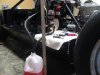
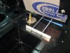
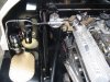
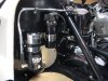
In an early post we noted that the car was ordered with “wings” or bulkheads located either side of the fire wall. We spent a lot of time laying out the location of the fuel pumps, coil and expansion tank. Our goal was to eliminate as much visible wiring and make the fuel system as simple as possible. We wanted to conceal the primary fuel filters behind the bulkheads. Full size patterns were drawn and revised several times as we experimented with the spacing.
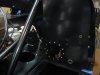
We wanted to be able to easily access the filters and electrical connections hidden behind the bulkheads. Although the bulkheads can be removed after the spider is in place, round access ports were added, using plates from AERO TECH LABS, part # TF107. They are about 4 ½” in diameter. They are pricey, but the gold alodine finish adds a nice touch and they are large enough to provide good access. The screw holes were drilled and tapped.
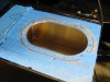
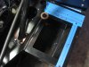
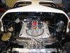
The small tank on the left rear was opened and an oval cover plate, approximately 6 x 9 inches from AERO TECH LABS, part #TF110A was used as a cover plate. Inside this area the gaudy bright MSD ignition module will be located where no one will ever see it, along with the fuel pump relays and other electrical parts.
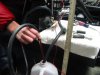
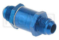
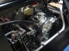
A layer of rubberized insulation / sound dampening was placed on the back of the firewall, which will be concealed by the bulkhead. Rubber grommets were placed where the fuel line and wires will pass through the bulkhead.
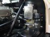
An aluminum angle bracket was secured to the chassis to hold the lower edge of the bulkheads in place. Holes were drilled just aft of the fuel tank (There is about ¾” between the back end of the fuel tank and the bulkhead – just enough space to secure the screws to hold the aluminum angle bracket.) Two six inch long by 3/16” screws were then run forward to the firewall to pull it back into position on each side.. Without these screws there is a lot of tension placed on the spider by the firewall.
In an early post we noted that the car was ordered with “wings” or bulkheads located either side of the fire wall. We spent a lot of time laying out the location of the fuel pumps, coil and expansion tank. Our goal was to eliminate as much visible wiring and make the fuel system as simple as possible. We wanted to conceal the primary fuel filters behind the bulkheads. Full size patterns were drawn and revised several times as we experimented with the spacing.
We wanted to be able to easily access the filters and electrical connections hidden behind the bulkheads. Although the bulkheads can be removed after the spider is in place, round access ports were added, using plates from AERO TECH LABS, part # TF107. They are about 4 ½” in diameter. They are pricey, but the gold alodine finish adds a nice touch and they are large enough to provide good access. The screw holes were drilled and tapped.
The small tank on the left rear was opened and an oval cover plate, approximately 6 x 9 inches from AERO TECH LABS, part #TF110A was used as a cover plate. Inside this area the gaudy bright MSD ignition module will be located where no one will ever see it, along with the fuel pump relays and other electrical parts.
A layer of rubberized insulation / sound dampening was placed on the back of the firewall, which will be concealed by the bulkhead. Rubber grommets were placed where the fuel line and wires will pass through the bulkhead.
An aluminum angle bracket was secured to the chassis to hold the lower edge of the bulkheads in place. Holes were drilled just aft of the fuel tank (There is about ¾” between the back end of the fuel tank and the bulkhead – just enough space to secure the screws to hold the aluminum angle bracket.) Two six inch long by 3/16” screws were then run forward to the firewall to pull it back into position on each side.. Without these screws there is a lot of tension placed on the spider by the firewall.

")
 Seriously, as Ron stated your work looks professionally done. Kudos.