Rear suspension bump steer

Since the post buy Tim OZ (Review RF85 8/2/06) I did some checking of my own.
I did some reading & swatting up on a few things.
So I’m not an expert in this area so hopefully I won’t say anything stupid.

A few things got said in the review that also gave a few hints as to where to look.
Thank you Russ Noble (my new friend).
The rear bump steer problem is 2 areas.
The hight of the front location of the trailing links (To high).
With the reverse A lower arm it shows up big time because of it general shape.

I had not given it much thought until now & the easiest way to explain is you are looking down at the car from above.
You string a line through the centre of the inner arm location point from the left to the right so you are 90deg to the centre line of the chassis.
The part of the arm that goes to the front location of the upright is pointing forward (a lot).
Now you have to look at the car from the side.
If the front location of the front link is high the trailing link will go through an arc as the rear is raised it will get longer untill it gets to the same hight as the front location point.

As it gets longer it pushes the upright back, because the lower arm pivots at the chassis from one pick up point(looking from the top again) it will push the arm back in an arc & make the upright toe out.

Looking from the top again.
If you run 2 equal length parallel links from the upright to the chassis instead of the arm.
If you imagine the chassis the links & upright make a box.
When the trailing link arcs and lengthens the box turns into a parallelogram.
Keeping the upright in the straight ahead position not like the A arm which will arc out.

Several days ago I put dial gauges on the rear end & checked for bump steer & was getting 2.5 mm of toe out through the working range of travel.
I did a dummy up using clamps & brackets, made some links ECT.
Straight away with an ordinary mounting set up it was down to .010” toe out.

So I cut the inner mount & did everything properly the out come is excellent & not what I would call major surgery.

The end result is at 2” of droop .010” toe in
1” drop .003” toe in
1” bump 0
2” bump 0
Toe in will add stability so its ok.
All these figures are with zero caster on the upright.

This is with zero caster
1.5-2 mm toe in.
1deg neg camber.

I have pretty much completed one side.
I have pics that might explain better.

This is how I went about it.
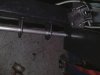
Pic 1 made a punch to mark the spot using bracket as guide.

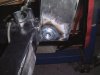
Pi2 machined spud with thread & weld in hole.

Pic2 Make brackets.
Made aligning tool to locate rear brackets.
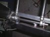
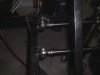
Pic3 links.

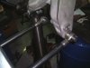
The front lower rose joint did go between the shock bracket & the upright.
To get it to line up to the chassis it had to be moved to the other side of the bracket & a spacer is fitted where it used to live.
I drilled all the link bolt holes in the upright to ½ “& put larger bolts.

If this can help anyone good luck.
 

Attachments

  • DSCF0114.JPG
    DSCF0114.JPG
    67.9 KB · Views: 1,793
  • DSCF0115.JPG
    DSCF0115.JPG
    55.3 KB · Views: 1,783
  • DSCF0117.JPG
    DSCF0117.JPG
    57.1 KB · Views: 1,760
  • DSCF0122.JPG
    DSCF0122.JPG
    50.9 KB · Views: 1,724
  • DSCF0118.JPG
    DSCF0118.JPG
    44.2 KB · Views: 1,671
Last edited:

Ross Nicol

GT40s Supporter
Hi Jim
You would have achieved zero toe change with suspension travel by cranking castor on the upright. When you set the castor to 7 degrees or so, the arcs the trailings arms scribe cancel each other and the upright doesn't move. Of course you've achieved a result with the links you've fitted but I worry this may cause some suspension binding during travel. A friend of mine fitted links as you have to his car and I had these concerns then too.
Ross
 

Russ Noble

GT40s Supporter
Lifetime Supporter
Hi Jim,

As I said a picture is worth a thousand words! Well done and nice work.

Ross. Horses for courses, there is no chance of anything binding with twin links but cranking on more caster is the easy fix to the bump steer problem at the expense of reducing antisquat. With reduced antisquat you can't get as much power on as soon, when you exit a corner. Given similar cars, say FF for instance, not only will everyone drive away from you in the second half of the corner you will also carry less speed all the way down the straight. If you've got more power than everyone else it doesn't matter so much, you're going to blow them into the weeds anyway!

The top links have absolutely no control over bump steer, the reason high caster minimises that is purely because more caster raises the front of the upright and the bottom trailing link becomes more horizontal and hence doesn't move the bottom of the upright fore and aft to the same extent as when there is a significant upward slope on the trailing arm. I would think there is more likelyhood of suspension binding due the excessive caster already using up 7 degrees of the available heim joint misalignment, but don't worry I think that is more a theoretical possibility than an actual one. If it was going to happen it would most likely be in the joint at the rear of the top radius rod at full bump if the joint is positioned horizontally. If it does occur it may be possible to eliminate by running the joint vertically.

Cheers
 
Last edited:

Ross Nicol

GT40s Supporter
Russ
I believe we are actually describing the same thing using different jargon. I understand you can change the anti squat/anti dive by shifting the trailing arm forward mounts vertically so we agree there. As I've said before though not easy to do when your chassis is all panelled in aluminium and no provision has been made for adjustment. Now I talk about the trailing arms scribing arcs which they do during travel and you talk about length. I agree that the t/arms will be at their longest when parallel (to the chassis rails) and will get shorter as they move away from parallel. Now because the t/arms are not parallel to each other, the top of the upright will be pushed and pulled as will the bottom of the upright but during suspension travel to bump this varying upright position can change the toe to out (not good). Now applying castor corrects this toe change but shifting the T/arms front mounts would achieve the same result.
Now the anti squat/anti dive is generally considered during chassis design and forward trailing arm mounts welded in during chassis construction so any adjustment in this area would be race car stuff, I think you'd agree.
So in my opinion for most GT40 replica owners changing the castor of the rear upright is the easiest way to cure bump steer problems.
Jim has fixed his bump steer by fitting solid lower links to the front and rear of the upright but with zero castor the T/arms will still be trying to alter the upright angle and this is why I suspect there will be some suspension binding.
Ross
 
bump steer

Ross
I also felt that that changing the front pickup points was a drama as well, it is a lot of work after you have sheeted the car.

I felt it was the best option for me.
I could have pulled on the caster but I prefered the way I went.

Without a doubt there is no binding.
I will be putting rose joints in all the links that have urethane.
But having said that it is that relaxed it would be fine with urethane as well.

When you say the upright is scribing an arc are talking about camber change or caster change.


Jim
 
Last edited:

Malcolm

Supporter
I just spotted this thread and wondered if there was some ancestry between GTD's and RF in suspension pick up points? I only mention this due to the first post above making reference to the effect of the height of the trailing arm pick up points.

On a GTD the height of the trailing arm pick up points is also critical with effects to the rear wheel. GTD chassis actually had two sets of holes for mounting the trailing arm. Use the wrong ones and handling does deteriorate. Some spins were known of before the word went round not to fiddle in this area.

Maybe a comparison of pick up points should be made to see if GTD knowledge is applicable to your concern? Just a thought
 

Ross Nicol

GT40s Supporter
Jim it's the trailing arms that scribe an arc as they move up and down thus changing the uprights caster. This in itself is not a problem but the outward changing Toe as a result is definitely a problem. As Russ points out and I think Malc is saying about the GTD, you can shift the lower trailing arm chassis pickup point to cure the toe change problem but I fixed mine with the caster setting of 7 degrees. Funny thing is this is the rear caster angle used in the original cars according to what I've read. I have a spherical bearing on the lower control arm inner and rose joints at all other points. Left and right hand thread rose joints in the trailing arms and top link make adjustment nice and easy. My explanation for the caster setting or adjusting the lower arm chassis point fixing the problem, is that the arcs scribed by the trailing arms cancel each other and nullify the toe change during suspension travel. My thoughts on what you have done by solidly locating the bottom of the upright Jim is that the arc scribed by the lower trailing arm as it moves up and down will be trying to move the upright but won't be able to. That's the problem I have with it.
Ross
 
rear end

Ross

Ok I see what you mean.
No it doesnt work that way with the seperate links with all rose joints.
If I remove the trailing links I can rotate the upright anti c/w & clockwise due to rose joint swivel.

When connected and it goes through its suspension travel the top link cancels the movement from the bottom link.
If you start out with zero caster you pritty much end up wth no caster change as I see it unless your trailing links are different lengths or a front location problem.

Like I said Im no expert on this I suppose if you have caster to start it will increase on bump as the top link
gets longer & the bottom shortens it rotates the upright back at the top and induce anti-squat as Ross explained.

The info is there for anyone to use (do your own checking before you cut anything off).
The work that people do on this site this job is not a big deal.

If the original cars had the same maybe they had a similar issue & they used the same fix.
Maybe these kit people have not only copied the shape but some of the pick up points as well.
Food for thought.

Jim
 
Last edited:
Ross,
Can I ask you to clarify a few points re your solution? I may have asked this before but can't remember your answer... but it will still be handy info for the forum anyway. :)

a) Is the 7deg setting positive? (ie. The top of the upright trails the bottom)
b) Which T/arm(s) did you alter to achieve the 7deg? eg both by equal amounts, top only, bottom only etc.
c) If top only or bottom only alteration, did the wheelbase change enough to be an issue with regards to the wheel’s proximity to the wheel arch?
d) And can anyone answer this. Will the existing inner/lower nolathane bush take that much adjustment?

Thanks in advance.
 
Jim
Ross makes a very valid point about the binding in the limits of travel. I have seen this problem with a lot of chassis set up for street driving....essentially a compromise between handling and less road noise and shock transferred to the chassis by heim joints. One bit I might add concerning the binding is that the upper and lower trailing arms (radius rods) don't just rotate about the mounting bolts, but also the rods themselves rotate around their axis slightly, which is a binding point if you are using urethane or some other bushing this becomes a problem...usually heim joints solve this, and I would use a high quality unit such as NMB or Aurora. Just my two cents.
Phil
 

Ross Nicol

GT40s Supporter
Chris your answers first
a/ Yes the caster is positive (top of upright rearwood of the bottom)
b/ I did alter the length of the trailing arms. The lower ones I fixed at a particular length to set the wheel base at 95". The top ones were then adjusted to achieve the caster for zero toe change (ie 7 degrees ).
c/ The wheelbase setting I used was RF manual figure and also original cars.
d/ I reckon the bracket on the chassis would have to be cut off and re welded at an angle to use the nolathane bush. Alternatively you could replace the nolathane with a rose joint or spherical bearing, then you could leave the chassis as is and only mod the lower control arms. Whether this would add to vibration/noise to the cabin I don't know because I've had bearings and rosejoints from day one. I have a feeling most noises are masked by the wonderful tune being played behind your left ear.

Jim
I'm pleased to hear you've checked for the cancellation affect. This is what I've been talking about.It wasn't till I put the caster on that the cancellation occurred and I got zero toe change with suspension travel. I think you said you changed the pick up point on the chassis of the lower trailing arm though and with zero caster that would be how you have achieved the cancellation.
Fixing the upright with the 2 lower links to stop the toe change is not necessary when you get the cancellation as toe doesn't change even with a swivelling inner bearing on the control arm. All this work I carried out with Will Croll an outstanding engineer inc (V8 Supercar background and RF systems design) and together we were able to understand how the rear suspension works and fix it. Altering caster to cure bump steer is explained in the book "How to make your car handle" by Fred Punh.

Phil
Thanks for the input nice to hear from you

Ross
 
bump

The pick up point has been moved but only further apart in effect it is still in the same spot.
It is still on the same plane.
Instead of being in the middle it is now 165mm apart.

The reason the bump steer goes with seperate 2 single links is the chassis the 2 links & the upright goes from a square to a parallelagram when pushed rear ward by the t/arm..
The single pivot at the centre as per std arcs back as the t/link length changes.
What it is doing by changing to 2 lower seperate links & yes all the others are rose jointed (no bushes).
It is changing the dynamic path of the suspension from arcing to parallelagraming if there is such a word.

With the original system you have to pull 7 deg to fix the problem which is fine.
With the 7 deg you are left in a position if you wanted to adjust how much squat or anti-squat (not moving front link hieghts) it cant be done at the back by adding or subtract caster as it will change bump steer.
With the links it allows you to change the caster to get squat & anti/s with no ill effect on bump steer.

It is the shape the 2 different designs travel through.
If Im wrong on any of this Im man enough to admit it but it seems to have
worked out.

Jim
 
Last edited:

Ross Nicol

GT40s Supporter
Hi Jim
Now let me see if I understand what you've done. You have moved the chassis pickup point for the lower trailing arm down. If thats the case you will have changed the anti/squat and may have had an effect on neutralizing the bump steer.
Now you've mentioned a good point because I was under the impression that the 2 links you have fitted would not allow the bottom of the upright to move back and forth but now I see yes it will and this is what you mean by the links forming a parallelogram when the trailing arm moves it back. This movement will happen until the rose joints neck out at maximum angle. Unlikely situation though. Ok so now I see you have controlled the Toe with these 2 links and the trailing arm will be able to go through it's arc without binding but there will be dynamic caster change, mmm more worms.
I get your point too about being able to change the anti squat now that your toe has been firmly set but I'll revert to my statement that anti squat is set by the chassis designer and as Russ says the power of a V8 will most likely over ride any disadvantage, incorrect anti squat settings on our cars may cause. After all Russ' example was Formula Ford and those things have very little power.
To wrap it up Jim you've done a lot of work which I agree now will work, but I'm sure most guys will be happy with what they've got, after correct adjustment.
Ross
 

Russ Noble

GT40s Supporter
Lifetime Supporter
Jim C said:
"I also felt that that changing the front pickup points was a drama as well, it is a lot of work after you have sheeted the car."

I don't think Jim altered the front pickups, that's why he went twin link and maintained the designed antisquat.

"After all Russ' example was Formula Ford and those things have very little power."

The point was not the lack of power, it was that they are close and extremely competitive and a good suspension setup is essential to success. They can't go out and buy another 10 or 20 bhp to overcome shortcomings elsewhere. And hell good suspension design and setup essentially costs no more than a mediocre offering. The gains are free!! If there was a field of thirty similarlarly spec'd GT40's out there you'd be going for all the improvements you could find!

You and Jim have both found different and satisfactory solutions to the same problem and both of you are equally happy the decisions/compromises/work involved. All car design is a compromise and it is up to the individual owners/modifiers/builders to decide what sort of trade off in gains and losses they are prepared to accept. Both cars will be miles better than "as delivered"
Well done to both of you.

Cheers
 
Last edited:

Trevor Booth

Lifetime Supporter
Supporter
Parallell lower links may well be suitable for the road but the ability to fine tune the rear suspension with +/- bump steer is lost. Zero bump steer is not always the best thing. You can change from oversteer to understeer by varying the bump steer at rear and or front. This is a desirable feature for circuit racing if you know how to use it.

You also need to consider the true radii of your suspension linkage as a single plane triangle. The true radii and hence the arc is normal to a line drawn thru the chassis pickup points.

The alignment of the clevis where the trailing link attaches to the upright is critical. It must be arranged such that you have a 3 link "wishbone" and not a 4 link "wishbone" This may have been Jims problem and the only issue to be solved.

What Jim has done is a substantial improvement over the original geometry which in its standard form is a geometrical disaster.
 

Ross Nicol

GT40s Supporter
Shit Trevor your first and last statements seem to contradict each other. "Desirable feature for circuit racing if you know how to use it" What a
throw away statement that is. I have documented a very practical development procedure on the rear suspension of my car, which has helped me take it from a terrifying track experience to a predictable to drive handler.
I may not have your engineering expertise but I know what's going on under my bum when I'm driving it. It's a rocketship in the wet (in other words the handling ain't bad) and it lacks power in the dry.
Results from last Sandown meeting 1st race 14th place dry
2nd race 4th place wet
3rd race 12th place dry

Mate I've been in electronics for 30 years and I can bullshit people with my
knowledge, however I choose to communicate with them at their level.
I don't believe you follow this principle. Sorry if I'm wrong.
Ross
 

Russ Noble

GT40s Supporter
Lifetime Supporter
Hey Ross,

Don't shoot the messenger particularly when he is agreeing that your setup provides ideal tuneability for track work! You've got a got thread going here and Trevor has brought up some further considerations worth exploring.

Trevor, you make some good points. Personally from a handling perspective, particularly for the road, at the rear I prefer toein on bump but I'm not sure that I agree with you that "Parallell lower links may well be suitable for the road but the ability to fine tune the rear suspension with +/- bump steer is lost." Parallel only applies in plan view in end elevation they need not necessarily be parallel. If you run the heim joints horizontally instead of vertically at the inner ends of the twin links and have them located by spacers between widebased pivots then by running different sized spacers top and bottom you can move the inboard pickup points up or down and tune your bumpsteer. It may need high misalignment heim joints to do this though. Is this what you mean by a "4 link wishbone" when the inboard pickup points are not in the same plane? This gives you your bumpsteer tuneability. What are the perceived drawbacks?

Cheers
 
design

Ross

Dont take this the wrong way and lets not start slagging each other and spoil this.
I put this up to show that you dont have to stick with what is there.
I have already said that I dont consider to be an expert.
I do consider Russ & Trever to be.

Ross we keep coming back to your set up.
I dont want your set up.
I already had that.
Let us listen and learn please.
Please .please

Gentleman enlighten us please
Jim
 
Last edited:
FWIW, i have contacted Jim to get a "kit" for my car. I think it sounds like a great idea. Start with the right geometry, and have full adjustability.
 

Ross Nicol

GT40s Supporter
Seems like I'm being ganged up on. I don't intend to shoot or flame anyone.
It just annoys me that you expose yourself by posting and then an expert comes along, makes statements and then doesn't give any explanation.
Anyway I'm off to work on my motor, bugger bump steer.
Ross
 
Back
Top