
You are using an out of date browser. It may not display this or other websites correctly.
You should upgrade or use an alternative browser.
You should upgrade or use an alternative browser.
Rear suspension bump steer
- Thread starter Jim C
- Start date
bump
If one lower link at the inner or outer pick up point had the ability to move up or down this would give you the ability to go toe in or out or nuetral on bump ?.
Jim
If one lower link at the inner or outer pick up point had the ability to move up or down this would give you the ability to go toe in or out or nuetral on bump ?.
Jim
Wasn't Jim Clark killed fighting bump steer at Hockenheim? That's a pretty drastic side effect!
Sorry, tongue in cheek. Almost before my time, I don't remember what the cause was. LOL. It WAS Hockenheim wasn't it or was that Rindt? Bloody alzheimers!
Cheers
Sorry, tongue in cheek. Almost before my time, I don't remember what the cause was. LOL. It WAS Hockenheim wasn't it or was that Rindt? Bloody alzheimers!
Cheers
"If one lower link at the inner or outer pick up point had the ability to move up or down this would give you the ability to go toe in or out or nuetral on bump ?.
Jim"
Yes. You would make the inner one adjustable rather than the outer one to keep the unsprung weight down. You've got to remember doing this will also affect your roll centre. But probably only a theoretical consideration. I'd like to hear Trevor's input.
You're a quick learner Jim.
Cheers
Jim"
Yes. You would make the inner one adjustable rather than the outer one to keep the unsprung weight down. You've got to remember doing this will also affect your roll centre. But probably only a theoretical consideration. I'd like to hear Trevor's input.
You're a quick learner Jim.
Cheers
It was a flat outside rear tyre that casued that crash. There were a stack of hypotheses including suspension failure and the like, but there was a comprehensive report somewhere that reported tyre damage consistent with having run over debris, resulting in ultimately "explosive decompression" of the tyre.Russ Noble said:Wasn't Jim Clark killed fighting bump steer at Hockenheim? That's a pretty drastic side effect!
Sorry, tongue in cheek. Almost before my time, I don't remember what the cause was. LOL. It WAS Hockenheim wasn't it or was that Rindt? Bloody alzheimers!
Cheers
Sir Jack Brabham believed this explanation, citing a previous instance where Clark hadn't detected a flat or deflating tyre, resulting in a largish crash... while Clark was and is regarded as the driver's driver, a natural behind the wheel, many (Brabham included) felt his "feel" for the car wasn't as acutely developed as many of his rivals.
Trevor, I'm still learning.
Could you please elaborate in more detail on your statement :-
"The alignment of the clevis where the trailing link attaches to the upright is critical. It must be arranged such that you have a 3 link "wishbone" and not a 4 link "wishbone" This may have been Jims problem and the only issue to be solved."
You've given us the information but I'm still unclear as to the nuances involved with the positioning of the clevis. Unless this is just another way of saying that with a reverse A arm you need to make every thing line up in the same plane which in this situation screwing on more caster does .
TIA
Trevor Booth
Lifetime Supporter
Ross N,
Engineers speak a funny language not always understood by the unwary. Its perfectly clear to me, I wrote it. If you need or want an explanation, just ask.
I have 40 years worth of grey hairs doing this stuff, and if you wish to compare notes about "places" you will need a thousand pens.
The 4 link wishbone Vs the 3 link wishbone. The "link" is an element in Engineer speak.
Consider the top trailing link, connected to the chassis at its forward end (A) and connected to the upright at its rearward end (B) via a clevis.
Consider the top radius rod connected to the chassis at its inner end (C) and the upright at its outer end (D) (Are you with me Ross)
Now draw an imaginary line through point A to point D.. If point B does not fall on this line you have a 4 element wishbone. If you have a straight clevis B will be outboard of the line A-D. The true radius through which the system pivots is about a line drawn from A to C. Just imagine what point B is doing as the system moves up and down.
Twin parallel lower links ( as Jim C ) will limit the "funny" movement of point B to some extent, but some geometric interference will result with a straight clevis.
Dependant on the overall geometry you may need to go thru a lot of wheel travel to notice this but it is still going on and stressing some of the elements.
Point B should fall on the line A-D to get a 3 element wishbone.
You may have noticed an offset clevis on suspensions of this type, the offset is to get point B to fall on the line A-D.
As far as raising or lowering the inboard end of one of the parallel lower links I have not done a plot but you would then have the lower points of the upright swing thru non concentric arcs tending to rotate the upright (in plan view) and displacing point B from the line A-D. Roll centre could be dramatically effected and I might suggest a loss of predictability.
If you recall your trigonometry, from days gone by, you can check all of this in a three dimensional co-ordinate manner. Me I use a 3D animated computer program and watch it happen in real time, saves remembering the trigonometry !!
Peter Delaney
GT40s Supporter
Does anyone remember that line from an old R&R song :
"Ego, its a dirty word"
"Ego, its a dirty word"
Hey guys, this is a really fascinating subject and one that I would like to learn more about, never having raced these suspension set ups in the rearend at least.
What would really work for me and I'm sure for others, is some line sketches or diagrams of the various geometry configs that you are discussing so that we can get where you're coming from. I sorta got it but need a bit of help visually.
Cheers guys, great thread...rockonsmile
What would really work for me and I'm sure for others, is some line sketches or diagrams of the various geometry configs that you are discussing so that we can get where you're coming from. I sorta got it but need a bit of help visually.
Cheers guys, great thread...rockonsmile
Trevor
While I have you.
I remade new clevises for my car .
I made them straight, They would fall outside A-D.
When I went to fit I realised the bottom required to be off set to pass the link through the chassis (donkey) so I remade the bottom off set.
They would fall on A-D
This is not to dissimilar to original position.
The top is outside & bottom inside.
So in effect it is 3 link on bottom & 4 on top.
Should I make all to 3 link.
What effect is this going to have having 3 & a 4
From what I see if I understand it top arm pivots through A-C to D
Bottom through A-D to C
Jim C
Last edited:
Trevor Booth
Lifetime Supporter
Jim,
Better off with 3 element system top and bottom.
Top swings thru A-C, radius is length of line 90 degrees to A-C passing thru D
At the bottom you have two C posn and two D posn C1 forward, D2 forward.
the swing radius of the system is a bit more complex
Initially swings thru A-C1 but then the C-D link modifies the radius to an imaginary point. if A, C1, C2 all on same line , much better but difficult to achieve.
I will get around to posting some sketches
10/10 for having a go!!
nota2266 said:At the bottom you have two C posn and two D posn C1 forward, D2 forward.
the swing radius of the system is a bit more complex
Initially swings thru A-C1 but then the C-D link modifies the radius to an imaginary point. if A, C1, C2 all on same line , much better but difficult to achieve.
That's easy for YOU to say.

Thanks for the offer of sketches. I'm goin' mad trying to keep up with all this...

I hope that this question isn’t too dumb, but something just doesn’t quite gel in my mind and I want to understand it before I make the (not insignificant) effort to correct the problem.
I’ve performed some very simple (and approximate) calculations to determine what sort of movements are required to get a 2.5 mm toe out with the current geometry and this is what I got…
All measurements are approximate.
• Distance from chassis pivot point of A-arm, to outmost point of the wheel is 750mm
• Distance from center of wheel to leading edge of wheel is 300mm
• Length of lower trailing arm 800mm
• Length of upper trailing arm 1000mm
Triangulating the required rearward movement of the wheel to the chassis pivot point of the A-arm, to achieve a 2.5mm toe out, the wheel must be pushed back 6.25mm
Triangulating the movement of the lower trailing arm to achieve this 6.25mm, the trailing arm would need to move through about 7deg of a radius, or 100mm of upward travel. But at the same time the upper arm would extend by about 5mm so the effective extended length of the lower arm is only about 1.25mm.
So to achieve a difference of 6.25mm between the upper and lower trailing arm, I did some progressive calculations and concluded that the wheel would need to travel a wopping 220mm of bump (lower trailing arm would sweep 15.5deg) to achieve 2.5mm toe out. But in doing so, the wheel would also need to be pushed back a wopping 30mm.
220mm of bump and 30mm change in wheel base sounds excessive and unlikely to me. Furthermore, only a fraction of that overall movement would be a contributing factor in destabilization during hard cornering, since the tyre will provide maximum grip when the suspension is loaded and already compressed. It seems to me that although the toe-out theory is true in principle, in practice there would be very little in it… or have I missed something?
Last edited:
I'll leave Trevor to answer the detail in this, other than to say did you take account of the fact that the lower trailing arm acts on the upright, not the outside of the tyre?
Cheers
Cheers
Cris
I suppose I should specify how I checked it to see if I have made a mistake.
Using the ride height and taking the distance between the eyes on shock mount.
I used that distance as 0.
I figure these cars will have about 25mm bump.
so I went 50mm drop.
When I tested I went 50mm either side of ride height.
I mounted a plate to the wheel hub 6mm thick.
On the plate I marked a centre line at hub centre.
either side of that another line at 200mm.
(only had one gauge)
The dial gauge was placed on both of these outside lines.
The height of gauge was never changed when moved.
Using a jack the suspension was sent through its motion taking measurements at every 25mm.
The readings from the front & rear where subtracted to get the answer.
The difference was .120" (2.5mm).
That was one extreme to the other.
Over 25 bump & 50mm drop
I checked it over & over and kept coming up with the same answer so could only presume that this is correct and the mode of testing is ok.
After modifiying to links did exactly same test & the results are as my first post.
Jim
I just got to work and checked the a-d-c link positions.
Because the front lower link has been moved back to get to a good spot on the chassis it has put both C points outside the Line.
Last edited:
Clayton
Supporter
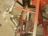
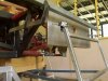
Hi Jim C
Love your work, sooner or later there will no original bits left on the car : )
I also went down the path of moving the lower inner pick up forward, still used the A arm though. Its interesting that I only needed 3.5 degs of caster to reduce roll steer, must be due to the different pick up location. (Ross has 7 degs).
So whats next on the hit list Jim ??
regards
Clayton
Attachments
Hi Clayton. Good to see you’re still hard at it and doing some great work.
CORRECTION! It dawned on me while I was lying in bed (where else) that my calculations were wrong. The upper trailing arm should not have been taken into account. Its only the lower arm that contributes to the dynamic toe. The upper arm only contributes to a dynamic castor. My calculations should have stopped at 7deg of lower arm swing corresponding to a 100mm of upward travel, (which is still wrong according to Jim C's measurements so I must still be out somewhere).
Rus, My estimates actually had the lower trailing arm acting on the axis of the wheel. Being only estimates, I figured it made little difference, but maybe not.
The other thing that dawned on me was that rotating the mounting bracket to allow for a nolathane bush would result in a different geometry compared to replacing the nolathane with a rose joint. This is because rotating the mounting bracket means rotating the axis such that the lower A-arm moves backward as it moves upward. That got me thinking. Would this be yet another solution to this problem? If so, you would get away with a castor of much less than 7deg.
nota2266 said:Jim,
Better off with 3 element system top and bottom.
Top swings thru A-C, radius is length of line 90 degrees to A-C passing thru D
At the bottom you have two C posn and two D posn C1 forward, D2 forward.
the swing radius of the system is a bit more complex
Initially swings thru A-C1 but then the C-D link modifies the radius to an imaginary point. if A, C1, C2 all on same line , much better but difficult to achieve.
I will get around to posting some sketches
10/10 for having a go!!
Trevor,
In an ideal world we have ideal solutions and I acknowledge that if you can build something that is theoretically perfect that is the solution to aim for.
But I am wondering from a practical perspective, where there is a 4 element wishbone, how much the lack of geometrical "purity" would affect the handling of the car? I'm referring here to the twin link setup not the "A" arm. I realise it throws an additional variable into engineering calculations but bearing in mind these points may only be offset a relatively small amount from the "ideal" position, won't the effect be minmal and predictable? Would a driver even notice it?
If the inboard end of the front parallel link was set slightly lower to promote toein under bump this will have the effect also of progressively lowering the rear roll centre, both promoting more understeer. And vice versa. Would raising or lowering that inboard pickup be another effective way to achieve a handling balance?
Is there any real life experience from anyone using this sort of setup?
Cheers
Last edited:
Similar threads
- Replies
- 2
- Views
- 562
- Replies
- 34
- Views
- 3K
- Replies
- 12
- Views
- 1K