
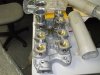
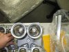
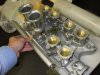
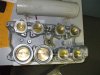
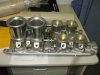
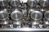
Just thought I'd share a few pics of the DC&O injection setup that arrived today. Very plesant distraction from work it was! Just gotta build a motor to do justice to it now...oh, and get car registered, and...etc.

You are using an out of date browser. It may not display this or other websites correctly.
You should upgrade or use an alternative browser.
You should upgrade or use an alternative browser.
8 Stack Injection Setup Pics
- Thread starter 200MPH
- Start date
Thanks for the tip Ricky. I'll try and remember that and keep checking for smooth throttle action when bolting up.
Will be a few months before the 'offroad use' motor is going though. Got the major components on order, hopefully here by end of month.
Had a couple of engineering (ADR) issues to work through, but have sorted them out. Just awaiting final approval for registration inpection presently.
Will be a few months before the 'offroad use' motor is going though. Got the major components on order, hopefully here by end of month.
Had a couple of engineering (ADR) issues to work through, but have sorted them out. Just awaiting final approval for registration inpection presently.
Peter Delaney
GT40s Supporter
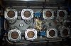
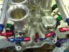
Wow Julian - looks very nice. It is also quite different from my older DC&O setup (see pics of a standard RF arrangement & my stripped down one below).
Apart from the T/B differences, I am wondering where the vacuum take-offs are (the old setup had a large vacuum plenum under the centre of the manifold, with 2 take-offs on the top towards the back). In the pic of my setup, one take-off goes to the braided hose at the top of the pic, & the other goes to the adjacent rubber hose. We started off with just the braided hose feeding everything, but had trouble with the MAP readings in the ECU when the power brakes operated - so we added the rubber hose from the 2nd take-off, left the MAP on the braided hose & put everything else on the rubber hose - solved the problem.
Also, you might want to look into a pair of water bleed points at the back of the manifold - the old one had none, so we drilled & tapped them in - they save a whole bunch of trouble with overheating & bleeding. These outlets connect to the braided hose at the bottom of the pic of my setup, & it goes to a nipple on the thermo housing.
Another thing - check the shafts for grooves that locate the circlips which hold the bearings into the T/B's - my shafts had no grooves at all on the shafts & so the circlips moved out, followed by the bearings ! Collets & spacer tubes solved the problem.
BTW, we changed our setup so that the fuel rails run up the inside of the T/B's - this was done to get the injectors to fire almost straight down the throats, rather than around a sharp corner. My engine designer came up with the idea that this would help to get a cleaner burn, & hence have a better chance at getting thru the emissions tests. It was a real pain to make new fuel rails & fit everything in, but it worked - just scraped thru the old ADR-79.01 tests on the 5th try (the only 8-stack ever to do so) !
Kind Regards,
Peter D.
Attachments
Peter - Thanks for sharing your experiences.
Two vac ports are in the manifold valley at the rear. You can see them in a couple of the photos. I don't know if I'll use either of them as I don't have power brakes and I may not be using MAP sensing for the ecu due to the large cam I've got.
I did note there are no rear water bleed ports, so I may follow your lead and add them in similar to standard ford efi manifold I'm using presently.
I agree regarding re-positioning the injectors, but don't think I'll do that as it will be a race only motor, hence light load/low speed driveability, emissions and economy don't rate for my purposes!
Julian
I have the exact type of 8 stack from DC&O too, and I did drill and tap for the water bleed ports too. The thing I love about this manifold is the single adjuster per bank and the fact that it is very uncluttered compared to the earlier types as shown in Peter D's photos.
Congrats on your purchase and hope it finds a suitable home soon.
Bill.
Attachments
Hi Guys,
Andrew here from Stack Injection, we are just signed up as a sponsoring vendor of GT40's and noticed your discussion on the DC&O manifolds. We are the exclusive online retailer for DC&O and in combination with their Manifolds are also offering a host of EFI equipment. You'll probably see our banner ad popping up here and there.
Check out the full range at:
StackInjection.com.au - EFI Individual Throttle Body Manifolds for Chev, Holden, Ford V8 Engines
regards,
Andrew
Kelly
Lifetime Supporter
Hi Guys, Check out the full range at:
StackInjection.com.au - EFI Individual Throttle Body Manifolds for Chev, Holden, Ford V8 Engines regards,
Andrew
Hi Andrew. That’s nice looking hardware. I have several questions relative to the 351W and 351C systems. Apologies if the information is already present at the website.
- I do not see any specifications on the throttle bodies. Are they IDA mounting patterns?
- What is/are the available diameters at the throttle plates?
- Is the 351C manifold offered in 2V port configuration or 4V? If 2V, does the manifold have sufficient wall thickness to be ported to 4V configuration?
- Is the 351W manifold offered in just standard 9.5 deck Windsor port position or are there any other port configurations offered?
Kelly
Hi Kelly,
Answers below in Red:
Regards,
Andrew
Answers below in Red:
- I do not see any specifications on the throttle bodies. Are they IDA mounting patterns? Yes they are IDA.
- What is/are the available diameters at the throttle plates? 50mm
- Is the 351C manifold offered in 2V port configuration or 4V? If 2V, does the manifold have sufficient wall thickness to be ported to 4V configuration? 351C is available in 2V, 3V or 4V
- Is the 351W manifold offered in just standard 9.5 deck Windsor port position or are there any other port configurations offered? Only standard 9.5 deck height is available.
Regards,
Andrew
Good that the 351W manifold has the IDA pattern. Means you have a few options for air filters from K&N and any number of filtration suppliers. The 302W setup has the velocity stacks touching and are fairly difficult to get a suitable high flow filtration solution. In the end I took the painful step of trimming down the trumpet outer lip diameters so I could force them through some rubber moldings on the bottom of some foam filters.
Decided I couldn't afford to kill the motor just for the love of looking at nice bare trumpets. Can always buy a spare set of trumpets and easily change over if I need the look for show purposes, cheaper than wearing out my motor too fast I think.
One other thing - a progressive throttle linkage is highly recommended to replace the standard cross type setup you get from DC&O. Very hard to apply small throttle openings smoothly otherwise.
Other than that, am happy with setup. Done just over 3000km of mostly competition driving.
Similar threads
- Replies
- 6
- Views
- 609
- Replies
- 74
- Views
- 6K
- Locked
- Replies
- 21
- Views
- 4K
- Replies
- 38
- Views
- 5K