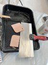
This stuff is amazing, thin and incredibly sticky

You are using an out of date browser. It may not display this or other websites correctly.
You should upgrade or use an alternative browser.
You should upgrade or use an alternative browser.
And so it begins...the AP build.
- Thread starter jlwdvm
- Start date
Yes. I’ve used it many times. Thin like packing tape but ungodly sticky.Does that tape hold up to polyester resin?
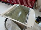
I see lots of body filler and sanding in my future, but this thing was a piece of garbage that was warped every which way before I started....and the opening was half as large as it is now.
Off topic, I’m building a frame like Arden’s with some twists, if I need some measurements could you pull them for me? Mostly relating to suspension pick up points. My body is ordered and c5 parts on the way.
Moving backwards to move forwards. This might be getting out of hand…or the piece was garbage to begin with. I decided to remove the spare tire bump, but the whole inner area has an arc to it with the high point in the middle. Pressing it flat would push out the sides. Cutting and heat didn’t really get me where I wanted to go, so I’m gonna remove the curved area, leaving a lip where it meets the sides. I’ll then bond the sheet I made to the snorkel area after get the appropriate curve to it. The panel is a layer of CSM and 1708, which should have plenty of flexibility.


Ian Anderson
Lifetime Supporter
Hey just thinking here
Should the inside bit not be curved twice? So bottom where is is behind the radiator it lies along the floor plate and then curves upwards and then curves the opposite way to match the top of the front clip?
Should the inside bit not be curved twice? So bottom where is is behind the radiator it lies along the floor plate and then curves upwards and then curves the opposite way to match the top of the front clip?
I just realized, I will have to put a bend in the bottom of the new sheet where it will meet the floor-bottom of radiator because it will want to return to a straight position when I remove the brace in the floor.
I also cut a slit in each side to the snorkel to take out the bend and allow the corners to be in position without tension and without the corner pins have to keep the panel down.


I also cut a slit in each side to the snorkel to take out the bend and allow the corners to be in position without tension and without the corner pins have to keep the panel down.
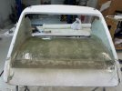
It’s kind of amazing how many twists and turns some of these seemingly simple projects take…and the time. I used some gutter screws to hold the new piece in place as the thickened epoxy cured. I tried to put a bend in the piece that is near the floor first. I felt the top was too stiff and too tight of a bend to epoxy in place at the moment. I’m going to trim it off and put a cardboard curve in the outside, and glass it to shape from the inside.


I applied the resin with a foam roller to each layer (CSF 1st layer, then 1708 on top with CSF side down) and then used a steel finned roller to get anything that looked like an air pocket out. I used 22oz of laminating resin for roughly 2 sqft. I rolled the hell out of it and am not completely sure why I have the white flecks in there, but i think they are areas between the sheet of waxed aluminum I used, and the 1st layer of CSF where resin didn't fill in. The voids will get filled with a thin coat of resin that contains wax to finish off the piece.
I got the top of the panel in place with some thickened epoxy, filled screw holes, and applied some to the bottom side to aid in the transition between the original piece and the new panel. I was starting to think this thing might end up in the dumpster, but I think I have something I can work with now that actually fits in the clam opening!


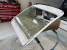
Applied 2 layers of 1708 and 1 layer of CSM to the bottom side of the new panel. Also applied a layer of finishing resin fortified with high density 404 filler to act as a glaze to fill any of the small imperfections in the panel. Used a cut down and slightly modified plastic spreader to shape the area where the new panel meets the sides. LOTS of sanding ahead!


Attachments
To make things go a little faster you can sand with 80 on an orbital, then spray gel coat with wax, at least a 2.0 tip. Sand and spray again, I find that’s a little faster than using filler etc because you get a nice even lay down. It’s also a mental leap because the panel while not completely flat, will look a little more finished until you get into final prep. The gel coat sands easy too.
Maybe my greatest accomplishment as a fiberglass fabricator…so far! Body worked the new sections. The transition between the new panel and the vertical sides of the snorkel took several spreads to get right. I think il going to use clay in the corners to add on the the snorkel and tighten up the gaps.
I’m not too thrilled with hose attachments on the rad. They seem to be an odd size. I might eventually remove them and change the size and angle.
And of course, the cups (near windshield) for the pins interfere with the foot box framing currently. Not sure if this will get better with final fitment of the front clam.
Similar threads
- Replies
- 11
- Views
- 2K