Bellcrank reinforcement plate ideas.

Ken Roberts

Supporter
I'm looking for help in designing bellcrank reinforcement plates. Pictures of what you have designed would be a big help. There have been reports of failure at this joint. My thumb and finger point to the two locations to join.

IMG_2079.JPG
 

Howard Jones

Supporter
Here's how I did mine. Just checked and I found no sign of movement in the pivot shaft, wear in the aluminum block in the chassis or the bell crank bearing. Seams to have worked well. The car has about 1500 track miles on it at this point. This mod was done while I was still building the car so all the time on the car is on this brace.
 

Attachments

  • HPIM2335.JPG
    HPIM2335.JPG
    861.6 KB · Views: 660
Man, it would be real nice if we could do a group buy on this part. Maybe we hire a 3rd party to weld up several sets to make them more affordable and not re-create the wheel? Mine haven't sheared on track but i'd rather err on the side of caution. Anyone else in?
 

Ken Roberts

Supporter
Ken. Craig S is in too. Ken would you be interested too, or want to make 4+ for cash?
I ordered some material from online metals to make a set. Each car might require slightly different dimensions. What fits one car might be a 1/8" too long or too short on another. There is no adjust-ability. I'll document the material I used and how I built them. You could then cut your own set and then have them welded up. I compared all the different styles and then decided on my own version to make it look factory made. Tried to make it as simple as possible as well. It will look similar to the ones in post#2.

I talked to one owner who tracks his SLC a lot. It failed and cracked the welds of the horizontal 2 by 2 frame member that the bell crank mounts to. The horizontal frame section had to be cut out and a new one welded in. Lots of work and expense. He reports that the section of square tubing should have been made thicker from the factory due to the stress it's under. It's only the same thickness as the rest of the square tubing at about 1/8" thick

Keep in mind thought that for street driving only you might be okay.
 
Last edited:

Howard Jones

Supporter
The problem in making parts for people is liability. Especially suspension parts. I would love to make up a batch and make them available but the risk is just too great. I am really sorry about that but at least anyone interested can follow the examples. Buy the way the post #2 car is the 25 hour blue car that competed in NASA quite successfully. I got my idea after looking over that car.

As an aside I think driving the rear antiroll bar from the other side of the bell crank counteracts the forces being applied to the bell crank shaft some what. This is done in three of the examples as well as the Green 01 RCR NASA car.
 
Last edited:

Randy V

Moderator-Admin
Staff member
Admin
Lifetime Supporter
Does the manufacturer recognize that there is a potential problem here?
What do they recommend as a solution?
 
Ken,
I have a track day coming up in a couple of weeks and would love to get this done before I hit the track. Are you close to having a materials list?
 
First time reading about this, some how I've missed this issue. I'd be in if anyone made or did a group buy.

If anyone has a sketch and dimensions of parts, I'd be glad to put CAD and share the file so people could get the pieces easily cut by water jet or plasma and bring them some where to get welded. Could make different lengths for each file so the owner can measure and just grab the correct file.
 

Howard Jones

Supporter
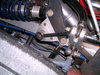
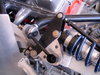
Here's the thing. This is a simple piece to make. All I did was cut off a piece of tubing with a large enough ID to allow the large shaft/bolt to clear through it. Then I welded on a thick washer onto the bottom. This piece was then put into place. Then I cut off a piece of 1/4" steel flat bar 11/2 inch wide and long enough so that the piece of tubing would clear the bolt head that secures the chassis brace. Once both pieces are in place a piece of 5/8 diameter thick wall (I think I used .125) tubing was cut to fit between the two and then tack welded in place. Then the assembly was removed from place and finish tig welded, painted, and put in final placement.

If you don't have a welder then make all the pieces, mark carefully, and have it done. As far a cad files go all you need is a hack saw and a electric drill.

Note: do each side independently to allow for variations.
 

Attachments

  • HPIM1888.JPG
    HPIM1888.JPG
    205 KB · Views: 587
Back
Top