
You are using an out of date browser. It may not display this or other websites correctly.
You should upgrade or use an alternative browser.
You should upgrade or use an alternative browser.
Bob's RF40MKII #134
- Thread starter Bobski
- Start date
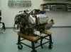
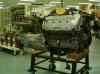
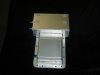
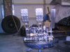
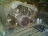
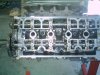
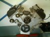
Here's a couple of shots of the motor in the shop before I bought it. I later on exchanged i for the 2003 supercharged motor but found it wouldn't fit (supercharger belt was inside cabin) so I went back to the original motor. Talkig about confusing the bloke behind the counter.
Attachments

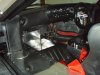
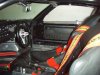
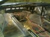
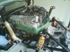
A couple of shots of the interior. Not finished a yet, as I need to form some aly to hide the aircon and intercooler hoses you can see on the drivers side. Got the aly, cut and all, just need to bend to shape and rivnut on. The seats were a custom make by RF and the drivers is moulded to me. Nice and snug. The six point harnesses are Sabelt and stand out a bit much, but since I can remember (boyhood dream) my car had to have these harnesses. Thinking of changing them to Willans ones to blend in with the interior a bit more, but I'm not sure. Opinions please. It hard to tell, but there is also a six point cage in there.
Attachments
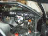
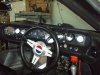
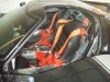
Looks mean and serious Bobski; I like it. With all the plain black and alloy, I think the bright harness colour looks OK in the photos. However, I'd have to see it in real life to see if it's too much.
What is sitting in the passenger's footwell? Is it a tank, or A/C unit, or what?
I plan to go to Warwick Farm for the Ford Day. I've got a Ford sedan, my brother-in-law has two Model T's, and I want to see GT40's thanks.
Regards, Dalton
What is sitting in the passenger's footwell? Is it a tank, or A/C unit, or what?
I plan to go to Warwick Farm for the Ford Day. I've got a Ford sedan, my brother-in-law has two Model T's, and I want to see GT40's thanks.
Regards, Dalton
Looks mean and serious Bobski; I like it. With all the plain black and alloy, I think the bright harness colour looks OK in the photos. However, I'd have to see it in real life to see if it's too much.
What is sitting in the passenger's footwell? Is it a tank, or A/C unit, or what?
I plan to go to Warwick Farm for the Ford Day. I've got a Ford sedan, my brother-in-law has two Model T's, and I want to see GT40's thanks.
Regards, Dalton
Hey Dalton,
You have a keen eye to spot that. Well your two guesses are both right! I call it a chiller box. It's where the intercooler water is stored and chilled by an inclosed A/C evaporator unit. It can be switched on and off at will or when needed to bring intake temps down. The cabin A/C has a seperate circuit and they operate independantly from eachother. Has this all been worth it? You bet. On a worm day the intercooler starts to condensate. On a 22degree day, after an hour on the dyno, the intake temps were dataloged on the Haltech and the highest recorded was 13degrees and average of 11degrees (belive it or not), we ended up switching it off to get the intake temps up so we can tune for safety. I will explain the full intercooler setup together with photos in the comming weeks. (trying not to get too far ahead).
See you on Sunday.

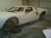
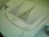
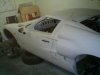
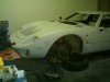
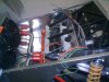
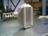
Here are some shots during the fun times of doing the bodywork. The RF's come verygood from the factory with double skinned doors and spider and with minimal ripples. The fibreglass is extra thick so it can withstand regular roaduse.
All the shutlines were closed up to 2.8mm - 3mm and the body was sprayed in Standox polyester, sanded back and then sprayed in Standox highfill. It stayed in highfill for approx 12 months while the rest of the car was built. Once ready for final paint, the body was guide coated a number of times before any paint was applied.
All the shutlines were closed up to 2.8mm - 3mm and the body was sprayed in Standox polyester, sanded back and then sprayed in Standox highfill. It stayed in highfill for approx 12 months while the rest of the car was built. Once ready for final paint, the body was guide coated a number of times before any paint was applied.
Attachments

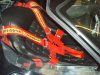
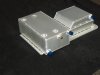
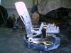
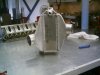
Time to get creative.
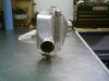
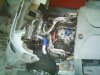
Because the original sump (oil pan) that the motor came with wouldn't fit and one couldn't be bought off the shelf, we had to design and make one. With lack of both finances and room, a dry sump wasn't an option for us.
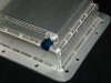
The new sump holds aprox 13.5L of oil, where the pick up is there are gates that let oil in and keep it in during cornering, braking and accelerating. The front sump is designed to let oil flow to the back sump during accelerating through the slot at the back and catch oil during braking. Best of all, the original pick up is kept and the windage tray still fits. It's a real work or art, shame thats it's hidden.
Because the original sump (oil pan) that the motor came with wouldn't fit and one couldn't be bought off the shelf, we had to design and make one. With lack of both finances and room, a dry sump wasn't an option for us.
The new sump holds aprox 13.5L of oil, where the pick up is there are gates that let oil in and keep it in during cornering, braking and accelerating. The front sump is designed to let oil flow to the back sump during accelerating through the slot at the back and catch oil during braking. Best of all, the original pick up is kept and the windage tray still fits. It's a real work or art, shame thats it's hidden.
Attachments
Time to get creative.
Because the original sump (oil pan) that the motor came with wouldn't fit and one couldn't be bought off the shelf, we had to design and make one. With lack of both finances and room, a dry sump wasn't an option for us.
The new sump holds aprox 13.5L of oil, where the pick up is there are gates that let oil in and keep it in during cornering, braking and accelerating. The front sump is designed to let oil flow to the back sump during accelerating through the slot at the back and catch oil during braking. Best of all, the original pick up is kept and the windage tray still fits. It's a real work or art, shame thats it's hidden.
That certainly is a work of art Bob, is it a Jim C creation ?
Thanks Tom,
The only place here I had some minor scrubbing is on the passenger door on the rear curved edge when you close the door. Now that the door aligned properly, nothing scrubs. I haven't had the painted car in the hot sun as yet, but I've driven it in a 38degree day in primer with the same gaps and didn't experiance any scrubbing then. Fingers crossed.
Regards
Bob
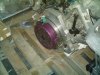
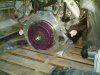
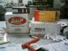
Photos of some of Jim C's creations. The quality of Jim C's work is second to none (unlike my photogarphy skills). The peddle box, radiator and rear clip (clam) hinges are all from Jim. I don't have photos of the radiator and the hinges, but will take some soon.
Attachments
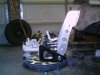
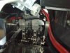
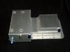
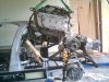
Some shots of the adaptor plate, preassure plate (clutch in background) mounted on the motor. All units supplied by RF. A photo of the motor and box going in for the first time, notice no sump as yet. Needed to get motor in to get measurements first.
Attachments
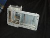
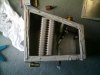
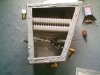
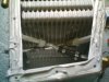
To get intake temps as low as possible, we needed to come up with a different intercooler setup. Originally I wanted to go with an air-air setup, but in a rear engined car, space is at a premium and a location to fit a large enough intercooler was prooving to be a problem. So we went for a water-air intercooler with a difference. Once the water oes through the intercooler, it goes through the water pump, through a tripple pass radiator mounted at the front of the car, and then through the chiller box which houses an A/C evaporator core. The water stays in the chiller box for approx 1 min beig chilled and then goes through the intercooler. I was hoping to achieve a 95% cooling efficiency, but our datalogging on the dyno shows that we are achieving over 100% cooling efficiency with the A/C turned on.
Water in one of the best mediums to absorb heat (approx 14 times better that air) but it's poor at loosing the heat. Through the design process, we made sure that the water spends majority of the time being cooled down than being heated. It takes approx 66 seconds for one complete cycle of water to be completed, and the water is being heated for only 2.5 seconds during that cycle. We tried a few pumps and ended up settleling for a 25L/min brass bodied pump ( off a boat used to wash decks) Originally the chiller box was made to hold over 30L of water, but had to reduce the size as we lost too much leg room in the passengers footwell. The A/C can be turned on and off by a switch and the cabin A/C works seperately. The A/C also switches off on full throttle and past 5,500 rpm so the compressor doesn't overspin. On a warm day, you can actually see the intercooler condensating as well a the chiller box. All I gotta do now is incoperate a beer cooler and I'm in business.
Water in one of the best mediums to absorb heat (approx 14 times better that air) but it's poor at loosing the heat. Through the design process, we made sure that the water spends majority of the time being cooled down than being heated. It takes approx 66 seconds for one complete cycle of water to be completed, and the water is being heated for only 2.5 seconds during that cycle. We tried a few pumps and ended up settleling for a 25L/min brass bodied pump ( off a boat used to wash decks) Originally the chiller box was made to hold over 30L of water, but had to reduce the size as we lost too much leg room in the passengers footwell. The A/C can be turned on and off by a switch and the cabin A/C works seperately. The A/C also switches off on full throttle and past 5,500 rpm so the compressor doesn't overspin. On a warm day, you can actually see the intercooler condensating as well a the chiller box. All I gotta do now is incoperate a beer cooler and I'm in business.
Attachments
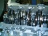
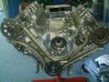
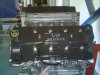
Some shots of the engine build. The pistons that we used are Mahle 16cc forged pistons. The rods are Scat H-Beam 4340 forged rods. The rings are Perfect Seal custom total seal rings. Bearing are King bearings and all studs are ARP. With zero deck height we ended up with a compression ratio of 9.0-1. Head gaskets are Felpro MLS type. The fuel injectors are 64pound and are limiting our final power output.
Attachments
![_DSC1416-2_2[1].jpg](/data/attachments/23/23310-b52b038af4b5732ba391e4402f3d2116.jpg?hash=tSsDivS1cy)
![080807_gt40-002[1].jpg](/data/attachments/23/23311-6017abda118447073091893bcd32b280.jpg?hash=YBer2hGERw)
![080807_gt40-069[1].jpg](/data/attachments/23/23312-aa62cf8766e925521227c683f259838a.jpg?hash=qmLPh2bpJV)
![080807_gt40-104[1].jpg](/data/attachments/23/23313-856b17b6940395386e98ef02515e0a1d.jpg?hash=hWsXtpQDlT)
![080807_gt40-123[1].jpg](/data/attachments/23/23314-deac761f5177134b0b69eadaf1c62cba.jpg?hash=3qx2H1F3E0)
Similar threads
- Replies
- 15
- Views
- 3K