I've mentioned the fuel tanks previously.
The left and right hand side tanks design capacity is 36.5 liters each, excluding the filler necks. Fuel flows from the bottom rear of them to a T connection and then through a non-return check valve into a small (11.5 liters) double triangular shape tank positioned in the front left hand corner of the engine bay. The intent of this is that there will always be a head of fuel retained in this center tank. An outlet from the bottom of the center tank connects through a shut off valve to a prefilter, then the fuel pump, regulator, filter and then up to the carburetor / s with a pressure gauge in the line.
A third connection at the bottom allows the system to be drained. The fuel supply lines are connected by -8 AN fittings.
The front top of the side tanks have -6 AN connections to breather lines that lead to the top of the center tank, with a third connection leading to a non-return vent valve to atmosphere.
The supply and vent connection lines to the right (driver) side tank are interrupted by shut off valves so that the car can be used with those closed and the right (driver) side tank empty, to give a fuel capacity of about 48 liters. For endurance racing the valves can be opened and the right tank also used to give a total fuel capacity of about 85 liters. The fuel gauge sensor is in the left side tank so as to read correctly in both cases.
I assembled the system on a bench and did a 0.5 bar (7 psi) soapy water test to check for any leaks, before fitting everything in the chassis.

The side tanks sit on insertion rubber pads on lower supports, with brackets to the front and rear to restrain against longitudinal forces. Rubber strips are fitted to the side chassis members that the tanks are pulled up to.

The side tanks are secured by stainless steel tension straps with rubber insert strips. The tanks are made from 2 mm aluminum and I was reluctant to weld mounting brackets to the larger tanks. The securing straps are positioned over where transverse baffle plates are situated inside the tanks.

Front of right hand side tank showing breather connection and removable forward tank restraint bracket.

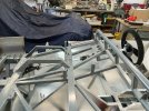
Left hand side tank and fuel supply parts in rear of side pod.


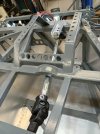
View of the system in the engine bay

On the right hand side what looks like the worlds most over engineered "P" clamp support bracket is also the mounting bracket for one of the water pumps.

Detail of center tank. This tank does have 3 welded on mounting brackets which are bolted to frame brackets with rubber washers between. Plumbing supply shops have a useful selection of rubber tap washers that can be used for this. This tank can be removed from the chassis with the engine in position, although you do have to remove the left exhaust manifold to do so.

Detail of the T connection from the side tanks . The black component is the one-way valve. It had a spring inside it which I removed so it functions only as a check valve.

Close up of the valve in the breather line from the right side tank.

To secure the valves and some other components to brackets I made up some mounting blocks. These are not CNCed, I started with some lazer cut 12 mm plate parts, and then linished, drilled and band sawed them. I had to drill and file recesses to allow the valve handles to fully open. The 2 halves of each block are stamped with an identifying letter so you can keep the matching halves together and orientated correctly. This as I drilled the mounting holes in a drill press before I cut them into halves.


This last component is the one way breather valve that will be mounted high at the rear of the car and connected to the top of the center tank. The center tank is slightly taller than the side tanks (excluding the filler necks) so will always have an air space at the top.

The total mass of the system is 22.8 kg (50.2 pounds), made up as below
Left and right tanks - 9.80 kg (21.61 p)
Centre tank - 1.87 kg (4.12 p)
Fuel filler caps - 3.74 kg (8.25 p)
Fuel level sensor - 0.22 kg (0.49 p)
Fuel filler spigots - 1.35 kg (2.98 p)
Fuel Filters, pump, hoses etc - 5.00 kg (11.0 p)
Tank mounting brackets - 0.80 kg (1.76 p)
The left and right hand side tanks design capacity is 36.5 liters each, excluding the filler necks. Fuel flows from the bottom rear of them to a T connection and then through a non-return check valve into a small (11.5 liters) double triangular shape tank positioned in the front left hand corner of the engine bay. The intent of this is that there will always be a head of fuel retained in this center tank. An outlet from the bottom of the center tank connects through a shut off valve to a prefilter, then the fuel pump, regulator, filter and then up to the carburetor / s with a pressure gauge in the line.
A third connection at the bottom allows the system to be drained. The fuel supply lines are connected by -8 AN fittings.
The front top of the side tanks have -6 AN connections to breather lines that lead to the top of the center tank, with a third connection leading to a non-return vent valve to atmosphere.
The supply and vent connection lines to the right (driver) side tank are interrupted by shut off valves so that the car can be used with those closed and the right (driver) side tank empty, to give a fuel capacity of about 48 liters. For endurance racing the valves can be opened and the right tank also used to give a total fuel capacity of about 85 liters. The fuel gauge sensor is in the left side tank so as to read correctly in both cases.
I assembled the system on a bench and did a 0.5 bar (7 psi) soapy water test to check for any leaks, before fitting everything in the chassis.
The side tanks sit on insertion rubber pads on lower supports, with brackets to the front and rear to restrain against longitudinal forces. Rubber strips are fitted to the side chassis members that the tanks are pulled up to.
The side tanks are secured by stainless steel tension straps with rubber insert strips. The tanks are made from 2 mm aluminum and I was reluctant to weld mounting brackets to the larger tanks. The securing straps are positioned over where transverse baffle plates are situated inside the tanks.
Front of right hand side tank showing breather connection and removable forward tank restraint bracket.
Left hand side tank and fuel supply parts in rear of side pod.
View of the system in the engine bay
On the right hand side what looks like the worlds most over engineered "P" clamp support bracket is also the mounting bracket for one of the water pumps.
Detail of center tank. This tank does have 3 welded on mounting brackets which are bolted to frame brackets with rubber washers between. Plumbing supply shops have a useful selection of rubber tap washers that can be used for this. This tank can be removed from the chassis with the engine in position, although you do have to remove the left exhaust manifold to do so.
Detail of the T connection from the side tanks . The black component is the one-way valve. It had a spring inside it which I removed so it functions only as a check valve.
Close up of the valve in the breather line from the right side tank.
To secure the valves and some other components to brackets I made up some mounting blocks. These are not CNCed, I started with some lazer cut 12 mm plate parts, and then linished, drilled and band sawed them. I had to drill and file recesses to allow the valve handles to fully open. The 2 halves of each block are stamped with an identifying letter so you can keep the matching halves together and orientated correctly. This as I drilled the mounting holes in a drill press before I cut them into halves.
This last component is the one way breather valve that will be mounted high at the rear of the car and connected to the top of the center tank. The center tank is slightly taller than the side tanks (excluding the filler necks) so will always have an air space at the top.
The total mass of the system is 22.8 kg (50.2 pounds), made up as below
Left and right tanks - 9.80 kg (21.61 p)
Centre tank - 1.87 kg (4.12 p)
Fuel filler caps - 3.74 kg (8.25 p)
Fuel level sensor - 0.22 kg (0.49 p)
Fuel filler spigots - 1.35 kg (2.98 p)
Fuel Filters, pump, hoses etc - 5.00 kg (11.0 p)
Tank mounting brackets - 0.80 kg (1.76 p)