CAV - Getting The Horsepower To The Ground - Part VII

It is not the same degree of intimacy as loaning your wife to a buddy for the weekend but it is close. After all the times your friends have patiently listened to you describe the fabulous performance of your GT40 eventually someone is going to ask to drive the car and experience nirvana for themselves.

That weekend finally arrived, tomorrow was a trip up to Prescott, Wickenburg, and 60 miles of twisty foothill roads.

The car was absolutely perfect and ready to make the best impression possible. It was spotless, paint and metal polished to a bright shine, gassed-up, and tuned to a razors edge without the slightest bit of roughness. Tire pressure, balance, and alignment were exact. The ride on the new freeway surface was virtually absent of any perceived vibrations as the car scooted along at 75mph flying 4 inches above the pavement.

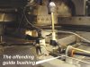
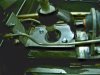
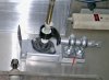
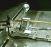
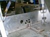
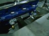
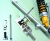
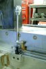
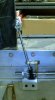
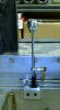
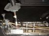
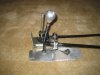
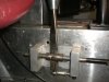
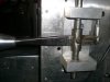
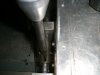
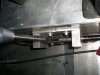
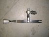
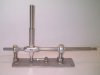
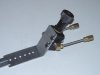
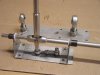
So what are the odds that the plastic guide bushing for the shift rod would pick that particular weekend and that particular morning to crack apart? The stock CAV Audi part shifter was ok but with the guide bushing loose it was now like shifting with a fly fishing rod. Even nirvana does not last forever. So here begins the tale of the CAV shift mechanism upgrade.
 

Attachments

  • CAV-Shifter-Stock.JPG
    CAV-Shifter-Stock.JPG
    248.5 KB · Views: 1,040

Ian Clark

Supporter
Hi Bob,

Great chatting with you on the phone today. I was wondering how you'd managed to break one of my shifters, however it was the old style CAV part that packed in.

In the past CAV Canada has offerred upgrades to the old (pre 100 s/n) CAV ZF shifter in the form of capture plates for the ball socket, replacing the rubber donut with rod ends etc.

We've decided to go the all dedicated, bolt in part route, rather than having to cut an weld bits of the shifter that came with the car. A bulkhead filler panel with hanger bearing is supplied to close off that area. The gasket gets looped onto the top of the new panel. Much quieter, cooler and cleaner.

The pics attached also show the latest shifter in an inline throw arrangement. CAVs typically call for the shifter offset to the right to clear the parking brake handle, however mechanism works the same. It is friction free and very precise.

There are different lever arms for the shifter depending on application. The bent looking lever is part of the soon to be released right hand shift kit that fits within the sill stamping on the right hand sill panel. Shifter stick can be any length you preffer.

Another logical upgrade part for any early CAV ZF car or if your going from a Getrag to a ZF.

Cheers
 

Attachments

  • Capture Plate.jpg
    Capture Plate.jpg
    261.8 KB · Views: 1,037
  • Revised Shifter v3.jpg
    Revised Shifter v3.jpg
    172.1 KB · Views: 997
  • CAVshifterCentral1.jpg
    CAVshifterCentral1.jpg
    181.2 KB · Views: 1,030
  • CAVshifterBulkhead.jpg
    CAVshifterBulkhead.jpg
    193.9 KB · Views: 991
  • CAVshifterBulkheadtoHanger.jpg
    CAVshifterBulkheadtoHanger.jpg
    220.6 KB · Views: 952
  • CAVinlineShifter1.jpg
    CAVinlineShifter1.jpg
    146.6 KB · Views: 1,000

Pat Buckley

GT40s Supporter
I got one of these from Ian - it totally transformed the sloppy imprecise shifting of the original to something that is a joy to use.

Highly recommended.
 
Everyone knows my bias that some threads should be about the sequence of the design process and the choices that go into upgrading our cars. How does anyone know what to do or what details are important unless real examples are provided along with the rationale for choices made. This is not information we are born with, and it does not automatically come with general automotive knowledge. There are times when I realize I am just reinventing the wheel, but the experiences of others at least keep me from reinventing the octagon.

The sequence of pictures that Ian added shows the evolution of his designs and are perfect examples of information that helps everyone advance. Hopefully other will also add pictures of shifter designs with some description of salient details. One of the really great things about owning a CAV is the number of truly talented people who have contributed to the designs for upgrade and alternate components that fit the original 100 seam-welded stainless steel mono chassis. They come from really diverse backgrounds and have all sorts of hidden talents and skills.

One GT40 buddy in Northern England is a dynamic figure, often seen scaling walls and crushing ice. He has been known to remodel train stations on his lunch breaks, making them more efficient in the area of heat retention. Another does charity work translating ethnic slurs for Cuban refugees. In France there is a person who likes to occasionally tread water for three days in a row and can woo women with sensuous and godlike trombone playing. There is a whole group of gear heads in the Northwestern United States who can cook Thirty-Minute brownies in twenty-two minutes. One is also an expert in stucco, another is an outlaw in Peru. California in particular is a gold mine of talented individuals with GT40 skills. My best contact there, using only a hoe and a large glass of water, once single-handedly defended a small village in the Amazon Basin from a horde of ferocious army ants. He has been the subject of numerous documentaries and on Wednesdays, after work, he repairs electrical appliances free of charge. An Italian “suspension consultant” who shall remain nameless has critics worldwide swooning over his original line of corduroy evening wear. But of course he doesn’t perspire. While on vacation in Canada, dashing and debonair GT40 owner from London once successfully negotiated with a group of terrorists who had seized a small bakery. After that experience he was reported to have even discovered the meaning of life, but forgot to write it down.

For this shifter project I teamed up with a friend in Sydney, Australia who is rumored to have won bullfights in San Juan, cliff-diving competitions in Sri Lanka, and spelling bees at the Kremlin. As for myself, I am a private citizen, yet I receive fan mail. As far as I am concerned, we are all beyond good.
 

Ian Clark

Supporter
Thanks Pat, Bob great stuff...

About the shifters. CAV Canada has completed the new Right Hand Shift mechanism to fit in the recessed sill box. Since the CAV has wider seats there is no room to run the shifter beside the sill, also running the shifter through the fuel cell portion of the chassis didn't appeal to me.

Previously in RHD applications a stainless steel open sided box hand to be welded into a pocket on the sill to make room for the original CAV/Audi shifter. Evolution being what it is, here we go...

The shifter mounts on a stainless steel plate that is tig welded (four smallish beads - no heat build up) to the side of the sill box. It has six tapped holes so the shifter can be positioned over a three inch range.

The shifter operates on a 1:1 ratio so it's as direct and travels the same arch across the shift pattern as if you had the genuine Ford GT40 type shifter in your car. The stick can be any length you preffer. Maybe a bit long in this pic, however it's the floor mounted stick just to get the pictures out.

So if you're building a RHD car and want to get away from central shift, or are in mood to convert your car to RHD, give me a call.

Cheers
 

Attachments

  • CAVrhdShifter1.jpg
    CAVrhdShifter1.jpg
    128.1 KB · Views: 872
  • CAVrhdShifter2.jpg
    CAVrhdShifter2.jpg
    103.1 KB · Views: 826
  • CAVrhdShifter3.jpg
    CAVrhdShifter3.jpg
    102.7 KB · Views: 816
  • CAVrhdShifter4.jpg
    CAVrhdShifter4.jpg
    105.4 KB · Views: 810
Last edited:
So here begins the tale of the CAV shift mechanism upgrade with the boring perfunctory parts first. The stock shift mechanism looks pretty much like what a big manufacturer would produce and put in a street car (see pictures above). It has a number of stamped steel pieces, custom injection molded bits, minimal welding, and no machining. And, at first, it was fine because I did not know any better. The shift rod was well supported from the shifter to the rod end in the bulkhead, to another rod end on the motor mount, and then to the ZF. Selecting gears was a little vague and felt more like an old Porsche than a Cobra. Slowly over time as the plastic and rubber parts wore down the shift pattern evolved from vague to Mr. Magoo. The big plastic and rubber donut bushing was the first thing to finally crack and get so loose that the shift pattern looked like this:
 

Attachments

  • Shift Pattern Evolution-2.jpg
    Shift Pattern Evolution-2.jpg
    32.3 KB · Views: 798
Here is a picture of my first attempt at replacing the cracked plastic bushing and tightening up the shift mechanism. It’s pretty much just an ugly patch on the stock shifter in an attempt to keep the horizontal transmission rod held rigid and only allow the tube to move fore/aft and rotate (no pitch or yaw). Interestingly enough this was the same change Ian also tried. I also relocated the entire mechanism a bit to the rear also so the shift stick was exactly centered in the console opening when in neutral. The u-joint was moved as far back as I could and the rod ends were located as far apart as space allowed. This patch made the shifting better than with the original stock plastic bushing but it really just encouraged me to see if it could be even better......
 

Attachments

  • CAV-trial shifter repair.JPG
    CAV-trial shifter repair.JPG
    261.2 KB · Views: 814
An alternative method of actuation is where the handle directly rotates the shaft and the fore/aft motion is controlled with a rod end. There is a u-joint welded to the shift rod and a rod end at the bottom. Plate structure is aluminium and the shift rod is a fine 1/2" all thread. This allows adjustment of the handle length to suit driver taste and the adjustment of the rod end "throw ratio" at the bottom. Works very well!
 

Attachments

  • IMG_0762_1.JPG
    IMG_0762_1.JPG
    98.1 KB · Views: 816
As best as I can tell there are only two basic “rod” shifter styles or methods being used on our cars. And now thanks to Ian and Gary we have pictures of both styles.

One design has a pitman arm attached to the transmission rod. The force to rotate the transmission rod, and move the rod back and forth is applied by the shift lever out AT THE END OF THE PITMAN ARM. The stock CAV shifter, and the examples shown by Ian, use that method.

A second method attaches the shift lever directly inline with the transmission rod so all the force applied for rotation and back and forth are exactly CONCENTRIC WITH THE TRANSMISSION ROD. The picture with comments posted by Gary is an example of the second method.

Each of these methods has some advantages which essentially are the subjects of this thread. As I worked with the stock CAV shifter I realized that the overall structural rigidity of the shifter is the key to a crisp feel and a no wobble shift pattern.

The first patch I made to the stock shifter was not enough. I added the two rod ends on a separate mounting plate, and then added an additional base plate just for more structural rigidity. The whole assembly was welded together and bolted to the stock mounting brackets on the floor of the CAV. The improvement was day and night but I was looking for perfection now.

Holding the transmission rod fixed, I could still move the shift lever and see the rod ends flex to the left and right and I could also feel the plastic parts in the pitman arm compress. This picture shows how the transmission rod on the unsupported shifter lever end acts like a pry bar to move the rod ends left and right.
 

Attachments

  • CAV-pry bar affect.JPG
    CAV-pry bar affect.JPG
    173.3 KB · Views: 777
As you can see I used the steering shaft plate mount ball bearings to the alum plates as well as a similar mount near the engine compartment bulkhead. I have a total of three shafts. First joint at the bulkhead next near the starter.
 

Ross Nicol

GT40s Supporter
Bob Here's my shift for the ZF which is the concentric 1:1 style. I got the design from a F1 Brabham circa 1973.The alloy blocks don't need to be that big but it works a treat.Teflon bush in each alloy block.The last pic is my original shift which I used for a couple of years. I believe the new shift which I've had for a year now is the ultimate, absolutely no free play and makes quick race shifting easy.
Ross
 

Attachments

  • gearshift old & new 001.jpg
    gearshift old & new 001.jpg
    62.1 KB · Views: 772
  • gearshift old & new 002.jpg
    gearshift old & new 002.jpg
    58.5 KB · Views: 726
  • gearshift old & new 003.jpg
    gearshift old & new 003.jpg
    51.2 KB · Views: 723
  • gearshift old & new 004.jpg
    gearshift old & new 004.jpg
    62.9 KB · Views: 721
  • gearshift old & new 005.jpg
    gearshift old & new 005.jpg
    64.2 KB · Views: 734
Ross,
Could you show a pic of the underside of the blocks. Is there another rod end under there to allow the rotation? Can't quite figure that part in my minds eye.

Bill
 
The pictures and comments being posted in this thread by Ian, Gary, and Ross sure show how we sometimes all get to the same destination each taking entirely different routes. There is a classic psychology experiment where a 20 foot glass wall is located in the center of a 30 foot long room. A thick line is painted on the floor around the glass wall. Food is put in the center of one side of the wall and a hungry dog, cat, or rat on the other. It doesn’t take long for the animal to learn to go away from the food and around the glass wall to get back to the food. All the animals learn this pretty fast. The interesting part is when the experiment is repeated with the glass wall removed. Almost all the animals, at least once, will continue to walk around the line on the floor to get to the food even though the glass wall is gone and they could have gone direct.

In this case, “gone direct” means to entirely eliminate the pry bar affect all I had to do was to place the supports for the transmission rod in front and in back of the shift lever. If the lever was between two wide spaced rod ends the pry bar effect is gone. Also, if the shift lever is operated concentrically on the transmission rod then the other offset forces from the pitman arm are eliminated.

Just like that guy on Mission Impossible who would look through his pictures and choose a strongman, a beautiful woman, and a midget juggler, I knew I needed help. Jim Cowden in Sydney Australia was the exact resource for this project. His company, Mental Performance in Sydney Australia, already had shifter products that could easily be modified for the CAV application. And besides, everyone knows that an expert only comes from some where far away. The first prototype from Jim was a straight forward combination of parts he already had on his shelf just to test the basic ideas in a CAV.
 

Attachments

  • CAV-Shifter Prototype 2 .jpg
    CAV-Shifter Prototype 2 .jpg
    151.4 KB · Views: 733

Ross Nicol

GT40s Supporter
The support in front and behind the gear stick is the solution to flexing of the gearshift rod. Quite a lot of pressure from the ratio of the stick is applied to the rod which I found was ok when pulling the rod but would flex it, when it was being pushed. I could feel the flexing when changing gear and totally fixed it with the new shifter. The reason I made the alloy blocks so large was to make absolutely sure the flex would be eliminated.I like Jim's design but I think a heavy hand could flex the rose joints IMHO.
Bill there is a male rose joint underneath the rear block and bolted to the block.Does that make sense? I'll take another photo for you if it doesn't.
Ross
 
Ross, I am absolutely shattered, not one piece of No 8 in that shifter of yours, you have been away tooo long !

Jac Mac
 

Ross Nicol

GT40s Supporter
What's No8 Jac Mac? Only joking of course you're referring to that fencing wire that fixes all things mechanical in the deep south of NZ.I've moved on Mate! I've discovered Gaffer Tape over here, but don't tell anyone or they'll all be using it.There is some wire in my shifter though if you look hard you'll see lock wire on the back side of the pivot bolt.To stop the bolt backing out.Scary thought I've nearly lived here longer than my time in NZ.
Ross
 
Here is a picture of the space available in a CAV for the shifter. The water radiator pipes are in the side pods and so there is more space available than in some replicas. Good news. On the other hand the brake bias valve on a CAV is mounted ON the stock shifter and it was now in the way of the front rod end of the prototype shifter. The easy solution was to just relocate the brake bias valve 3 inches forward on its own independent mounting bracket. It can be mounted standing straight up like in stock form or it can be tilted back toward the driver with the knob ending up more in the original position. Good news again.

Shifting was absolutely transformed with Jim’s basic prototype. It worked exactly the way Gary and Ross both described for their own versions of this concept. I love the simplicity of the design but Jim and I both thought it needed to go on a diet.
 

Attachments

  • CAV-Shifter Mounting Brackets.JPG
    CAV-Shifter Mounting Brackets.JPG
    380.6 KB · Views: 718
  • CAV-Brake Bias Valve Bracket.JPG
    CAV-Brake Bias Valve Bracket.JPG
    187.3 KB · Views: 693
Last edited:
Supporting the transmission rod between two big rod ends is convenient but unnecessary. Since they are always perfectly inline, they could be replaced with plain bushings and Teflon inserts. Likewise the long heavy base could be replaced with a shorter cradle that held the Teflon bushings at each end. The small rod ends that stabilize the bottom of the shift stick were retained. Here is the next step in the sequence of making a trimmed down prototype.
 

Attachments

  • CAV-Shifter Prototype 3.JPG
    CAV-Shifter Prototype 3.JPG
    255.7 KB · Views: 730
Back
Top