CAV - Getting The Horsepower To The Ground - Part VII

Pat Buckley

GT40s Supporter
Bob,

Surely as the shift rod goes back and forth it will go up and down as it is going to make an arc that is centered on the lower rod end? O isn't the travel enough to make this an issue?
 

Ross Nicol

GT40s Supporter
Bob- I reckon you need to bring the bushes closer to the shifter. I worked out the travel required then allowed some clearance.I also think you need to reinforce the bush mounts with longitudinal gussets. I still like my alloy blocks but maybe retain the thickness and trim down the width.
Ross
 
That is why my rod ends go through the one plate to minimize the unsupported length. When I am in 3rd gear there is little clearance with the ball. Alignment of the system is relatively easy as I only have to get close. The rod I used is 3/4" hollow shift steering rod and bending is not an issue with the given forces. That is why I went with the welded U-joint at the shifter that require zero machining of custom parts. Plates are fairly easy to cut and weld.
 
You guys are really right on top of this!

Excess material was trimmed and the assembly was welded together. Gussets were then added at each end to eliminate flex in the end plates. This version holds the transmission rod firmly in place, and like Ross observes, must keep the transmission rod from bowing under the leverage of the shift stick.

This picture is essentially how the shifter is positioned with the shift stick in neutral. For the ZF transaxle, the transmission rod must have enough room to move forward and backwards about 3/4“ in each direction. The rise in the small rod ends at the bottom of the shift stick is very minimal.

The neutral position of the shift stick must also be centered in the console opening. The small rod ends at the bottom of the shift stick are used to make these adjustments. Next the end of the transmission rod on the shifter is cut to the correct length to connect to the u-joint going to the transmission which should also be in neutral. (I think this positioning sequence applies to all the versions of shifters.)

Here are pictures of prototype #4 on the bench and installed in the car.
 

Attachments

  • CAV-Shifter Prototype 4.JPG
    CAV-Shifter Prototype 4.JPG
    278.3 KB · Views: 587
  • CAV-Shifter Prototype 4 Installed-1.JPG
    CAV-Shifter Prototype 4 Installed-1.JPG
    292.1 KB · Views: 585

Ross Nicol

GT40s Supporter
I like it Bob but if #5 ever gets designed I'd use 1" alloy blocks bolted or welded to a 1/4" alloy bottom plate as wide as space permits.I can see those bushes as they are, still flexing.I could be wrong though. I believe when racing the gearshift gets a lot of force and rough treatment so this is why my early gearshift was hopeless.A baulking gearshift costs you so much time.I know a lot of you guys will never race your cars so a gearshift beefed up to the level of mine may not be required, however the word ultimate surely describes an overdesign and that's what I believe I have. I would also add that the ZF does not have a light and delicate gear selector and when you run 1:1 ratio at the shifter, gym membership is not a bad thing.:lol:
Ross
 
Just as Ross suspected, pictures of prototype #5 are inline to be posted next.

But, first I wanted to report on some limitations of #4 and explain why #5 was needed. The totally concentric, minimal component design of #4 is really rugged. It can be used in the center console or on the sills. The force needed to make the shifts is proportionate to the length of the shift stick above the transmission rod and the length below the transmission rod. Prototype #4 has a relatively long shift stick and so the force to make the shift is much less than if the stick was shorter. On the other hand, the absolute distance the top of the shift knob moves from 2nd to 3rd is about 8 inches which is a long throw. If the shift stick was shorter the force required would be more but the throw would be shorter. Clearly a trade off. Goal 1 - Jim and I thought prototype #5 should have a shorter throw.

The second limitation is entirely a CAV issue. All of my testing so far has been without the fiberglass center console installed. The first picture shows how the car was driven for a few weeks so I could test and watch the shifter in routine use (first picture). As I said, I thought the shifting was as excellent. With the console installed however, the range of motion of the shift stick was almost too large to clear the chrome ring on the stock CAV console. Left/right clearance was fine but fore/aft only had about 1/8” to spare (second and third pictures). Jim and I both thought this was way too tight a fit. Initially we thought that if the entire shifter and cradle was raised then the shift stick would clear the chrome ring and it did. Unfortunately it also made the u-joint and transmission rod rub the underside of the console. Goal 2 - Find a solution to get more clearance at the chrome ring and inside the console.

Although prototype #4 is adequate, it would not hurt if the cradle was stronger. Jim also thought this was required. Goal 3 - Beef up the entire cradle structure. (Goal 3 1/2 is never let Ross design jewelry, especially earrings with all this talk about 1 inch thick aluminum blocks.)

Because I like Pat, and he was concerned about the lift of the rod ends on the bottom of the shift stick we will add: Goal 4 - Reduce the lifting and arching of the lower rod ends.

And finally Goal 5 - Preserve about 1 inch of fore and aft adjustment so CAV cars with slightly different console measurements would still have enough play to center the shift stick in the console opening. And again, Jim votes for an easy way to get the alignment adjusted.

This is where the Mission Impossible part comes in.
 

Attachments

  • CAV-Shifter Prototype 4 Installed-2.JPG
    CAV-Shifter Prototype 4 Installed-2.JPG
    143.3 KB · Views: 590
  • CAV-Shifter Prototype 4 1st Gear Clearence.JPG
    CAV-Shifter Prototype 4 1st Gear Clearence.JPG
    281.3 KB · Views: 564
  • CAV-Shifter Prototype 4 4th Gear Clearence.JPG
    CAV-Shifter Prototype 4 4th Gear Clearence.JPG
    292.5 KB · Views: 563

Ross Nicol

GT40s Supporter
Yep I'm not big on jewellery, won't even wear a wedding ring.Is mission impossible the inability to get your hands in to adjust the rose joints. I built the rest of my shift rods while keeping the shift centered. Failing that why don't you fit a threaded section into the shift rod in the engine bay for stick centre adjustment. When you get to #10 you will be close to the number of designs I went through. It's amazing how such a simple looking device can throw up so many challenges, but I refused to let the thing beat me and it didn't.
Ross:)
 
One way of getting the rod to work with such a small hole is to mount the upper pivot as close to the underside of the hole as possible and have the rods all clear. That is what I did. Can maintain a larger throw and still have room.
 
Accomplishing Goal 3 to beef up the cradle was a no brainer. The thickness of the material used was upped from 2mm to 3mm thick stainless steel. All the pieces were laser cut with matching tongues and grooves then jig welded.

To do Goal 4 the aft rod end was relocated farther back between two gussets.

The Teflon lined bushings were made removable and with a bit of adjustment room to resolve Goal 5.
 

Attachments

  • CAV-Shifter Prototype 5 Cradle.JPG
    CAV-Shifter Prototype 5 Cradle.JPG
    125.3 KB · Views: 527
  • CAV-Shifter Prototype 5 Cradle Bushing.JPG
    CAV-Shifter Prototype 5 Cradle Bushing.JPG
    195.4 KB · Views: 537
  • CAV-Shifter Prototype 5 Rod Ends.JPG
    CAV-Shifter Prototype 5 Rod Ends.JPG
    349.7 KB · Views: 531
The unifying solution to Goals 1 and 2, to reduce the throw and clear the chrome console ring was solved by Jim in one step. (The rumor is that the idea came to him late one night after a Chinese food dinner of Bia Lo Sell Hai in crispy aluminum foil.)

Basically Jim added an extremely structural triangular riser to the center of the transmission rod. The sides of the pivot slot were functionally raised. The shift stick pivots fore and aft at the top of the riser above transmission rod but is still concentric with the transmission rod for rotation left and right.

The net result of this change in geometry was that the fore and aft throw was reduced to under 5 inches and left and right rotation stayed the same. The shift stick now has room to spare on all sides in the CAV console opening. This picture is of the “final” prototype. My big leather Sparco gear shift knob is mounted on the shifter and a smaller traditional GT40 style knob from Jim is in the background.
 

Attachments

  • CAV-Shifter Prototype 5.JPG
    CAV-Shifter Prototype 5.JPG
    278.3 KB · Views: 540
Here is the shifter assembly installed and properly aligned in my car. There is room on the transmission rod to locate the shift stick an inch more forward or rearward if required by any particular car. The front and rear Teflon bushings could be reversed and mounted extending to the inside of the cradle to make more room for the brake bias valve or the rear u-joint connection if needed.
 

Attachments

  • CAV-Shifter Prototype 5 Installation-1.JPG
    CAV-Shifter Prototype 5 Installation-1.JPG
    315.3 KB · Views: 570

Ian Clark

Supporter
Hi Bob,

I'm really enjoying this post, talk about the mother of invention... wow! It's great to see other solutions to the problem and also the evolution of parts. Some days it's good to know I'm not the only one banging his head on the wall!

There's more than one way to skin a cat, but since it's now politically incorrect to describe the methods, I'll stick to race car parts:)

The shifters shown by Ross and Gary are brilliant too.

I struggled with using a lever arm vs a slotted shifter and lower link/pivot. No doubt all formats work, I had to live within the unique packaging requirements of the CAV console or right hand sill panel so the direction we chose was designed to keep the parts count down, the installation as painless as possible and the whole affair maintaince free.

Still, I can't say enough about how impressive the stuf is forum members come up with - and the overall body of knowledge here for GT40 enthusiasts:)
 
I think this design is a bulletproof piece of R & D. The shifting feels totally definite and greatly contributes to the experience of driving the car. And, with the console installed, everything looks and feels correct.

In these pictures the leather hood that goes around the shift stick has been left off so the mechanism inside the console could be seen. You can also see down inside the shifter itself. I thought Reverse and 5th gears were the most extreme positions so I have included pictures of the shift stick in those two positions. There is 1/2 inch clearance on the sides and a little more that 1 inch at the front and back to the chrome console ring.

All-in-all the shifter project has come to a very satisfactory outcome. I imagine now that all the fitting and testing has been done, a production version of the shifter will be available from Jim.
 

Attachments

  • CAV-Shifter Prototype 5 Installation-2.JPG
    CAV-Shifter Prototype 5 Installation-2.JPG
    360 KB · Views: 492
  • CAV-Shifter Prototype 5 Reverse Clearence.JPG
    CAV-Shifter Prototype 5 Reverse Clearence.JPG
    318.6 KB · Views: 504
  • CAV-Shifter Prototype 5 5th Gear Clearence.JPG
    CAV-Shifter Prototype 5 5th Gear Clearence.JPG
    318.5 KB · Views: 506
I won’t go into the relatively standard details of the shift linkage routing back to the transmission except to show two pictures of the adjuster I use at the ZF. Original cars often have a universal joint that incorporates two flanges bolted together. The fore and aft position of the linkage (and the new shifter) can be set by adding or subtracting spacers between the flanges. My clone part is the second picture. A stubby splined shaft also comes out the front flange and goes into the mating end of the universal joint so rotation can also be set. This little gismo makes after-the-fact adjustments much easier.
 

Attachments

  • Shift Linkage Adjuster.JPG
    Shift Linkage Adjuster.JPG
    289.1 KB · Views: 516
  • Shift Adjuster Clone-3.JPG
    Shift Adjuster Clone-3.JPG
    306 KB · Views: 469
Last edited:
This pretty much concludes Part VII and the shifter project. My wife asked if finishing the shifter meant that now my car was all done and we could go to more art museums. I said that if I was lucky it would never be done. She was thrilled.

Thanks to everyone who added pictures, descriptions, and suggestions to this thread. And a special thanks to Jim Cowden for help with this long distance project. It turned out to be a very good working relationship in which he added the lion’s share of technology. I have nothing but good things to say about Jim and his insight into what makes a good design.

For the next project I have something in mind for the front of the car if only I can only find an expert in jazz yodeling, but that is another story.
 

Attachments

  • CAV-Shifter Prototype 5 Installation-3.JPG
    CAV-Shifter Prototype 5 Installation-3.JPG
    364.5 KB · Views: 486
Hi Bob,
I really liked your shifter design. So I have two questions, First can anyone purchase this shifter, or is it a one of a kind? And second if one could be purchased, How much is it and whom do I contact?

And thanks for sharing your improvements on your car with all of us!
 
Kenny

I have not put it on my site as yet, over the next week or so I hope.
Happy to make one for you.

I have sent you a PM.

Jim
 
Last edited:
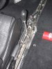
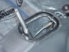
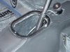
I have a question on an earlier post/picture. In Ian's post of 3-17 he wrote of the original problem with the guide bushing going bad, and causing sloppy shifting. I have thought this over for some time as I am designing a rod shifter myself, and have followed your progress though the postings. However, here is my thought. The proplem with the original bushing was never really talked about as to why it failed. It took me back to my 9th grade geometry classes. Glad I paid atention then.
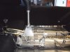
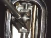
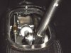
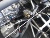
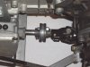
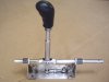
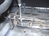
You show the original rod as aiming off to the side and going through two different bushings after the failed bushing. I think therein lies your problem with that bushing. Don't get me wrong for the improvements have been simply great and will help out the other CAV owners, and other ZF guys with their shifters. Whay is wrong to me is that you have the rod going off at an angle and held firmly in its position by the three bushings. When you shift forward or backward there is a torque on those bushings. The rod wants to go in the same direction, but it is not allowed to because it is aimed off in another direction, putting a thrust onto the bushing. With the new and improved version, which has the rod held in front and behind the shift lever, this seems to be even more pronounced than with the old shifter. It is sort of like a parrallellogram in a way. the piece connecting the two parrallel rods wants to move in the same direction but can't because it is held in place. If it is allowed to move forward and back in its own direction, it will cause a bind further down the line. Has that piece been changed? If not , it seems to be the next area of failure. I don't know if I am making this clear or not. If not I will draw it out and post the drawing. This is a real problem for us all since we only have about 15 degrees to play with on the universals. Maybe a few more pics are needed to see how the rods are aligned, and my not needing to be concerned. Just a thought.

Bill
 
Bottom line is get rid of most if not all plastic in the design. Flexibility in directions not intended in the joints and bushings is bad.
 
Back
Top