Chassis supports fore rear clip

I'm to the point where I need to start thinking about how to suspend the rear clip. I've seen some photos of the apparatus that mounts to the body itself, but how that mounts to the chassis I don't see many images of.

I was thinking about something like in the drawing attached. My chassis has a rectangular area where the transaxle is located. My thought is to add a 28" section of angle steel to that rectangular area, then a 15" or so (whatever the length needs to be...probably make it adjustable) section to each end of that which will hold a 58" section of angle steel. On that at each end a piece of steel will project upwards and attach into the apparatus that is attached to the clip itself.

Does this look anything like what others have done? If so, what thickness of steel is typically used? I'd rather not add any more weight to the end than is needed so I'd like to go with thinner angle steel, maybe 1/8" if possible.
 

Attachments

  • RearConfiguration.jpg
    RearConfiguration.jpg
    5.5 KB · Views: 278
Not sure what you are asking for. Are you trying to attach the clip to the frame/framework at the back of the car? Or are you talking about supporting the rear clip when it is open. If it is the former. I can supply some pics of that part of mine. It is quite simple really. Just two bolts and that is it. The tricky part is getting the clip at the right position to make the framework for it all. For propping the clip up I use gas shocks.

Bill
 
Supporting the clip when it's open as well as supporting it when it is closed. Here is a photo of a nearly identical chassis to mine (and is identical in the rear). Notice that there is no way on it to support a clip at the present. You have to add metal brackets, or bars to support the rear of the clip.
 

Attachments

  • PICT0096.JPG
    PICT0096.JPG
    228.6 KB · Views: 256
Here are some pics of my assembly. Will send more detailedd ones later.

P1010028.jpg


P7040211.jpg


P1010285-1.jpg


The second pic shows the bolt hole for the body mount. Will take some pics of the body attachment pieces later today as I have the rear clip off the car for painting.

Bill
 
This is AWESOME Bill. Thanks!

Did this come with your kit or was it added later? The photo with all of the components makes it look like it was a separate thing in which case I might be able to purchase one similar after checking for fit.

Also, do you know what metal specs are and its thickness?
 
Last edited:
Will measure the thickness when at home. It basically is 1x1 stock. Not sure any of the ends are open so may not be able to measure. Will measure the lenghts and distances tonight and will fix up a pic with the dimensions. Will do the same for the rear clip. Your mounting points may differ based on where your vertical supports are on the clip and frame width. It will get you started at least.

Bill
 

Ian Anderson

Lifetime Supporter
I have thought about this and would consider doing it with three turnbuckle arrangements per side so the final mounting point can be adjusted up, down, forward, rear, left or right by a few mm to aid in rear clip alignment.

With a left And right hand thread on each bar you could get exact positioning of the mount points in all three axis

Ian
 
Will measure the thickness when at home. It basically is 1x1 stock. Not sure any of the ends are open so may not be able to measure. Will measure the lenghts and distances tonight and will fix up a pic with the dimensions. Will do the same for the rear clip. Your mounting points may differ based on where your vertical supports are on the clip and frame width. It will get you started at least.

Bill

Thanks Bill. I have some 6061-T6 square aluminum tubing in 1.5" size and .125 thick that I think will work nicely so don't sweat it if you cannot measure the thickness. GREATLY appreciate the lengths of course!
 
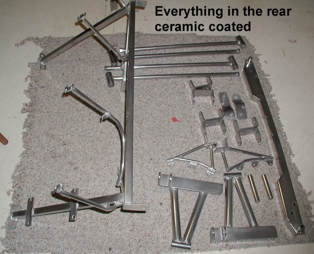
First the pics and then the explanation of the shots.

PB220166_zps32969ce1.jpg


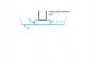
17" is the outside of my frame.
38" is the outside of the horizontal bar including the mount for the body. The tabs are about 4mm. This bar is square to the link going down to the frame
36" is the outside measurement of the link to the top of the cross engine mount.

PB220165_zps8fffea55.jpg


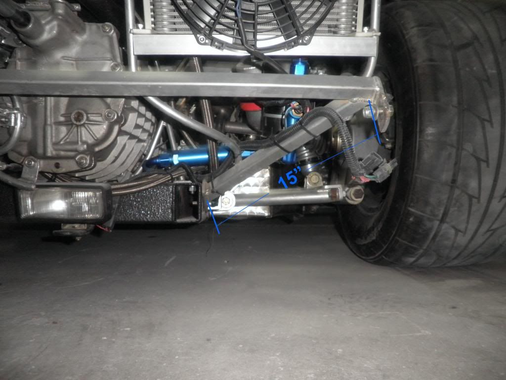
15" is the bottom link and is measured from its weld to the horizontal bar to where it meets the tab on the frame.

PB220164_zps9e779529.jpg


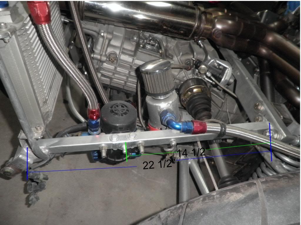
22 1/2"is from the end of the bar at the body mount to the cross motor frame member. The tab on this piece is thinner than the regular tabs. About 2mm
14 1/2" is the mount for the gas shock. The shock is a 40# shock(ebay). Measure the distance from the frame mount to the body mount with the clip open to the position you want it to be open. I chose the point that the clip was just short of being balanced. Measure same when closed. Hold the link mount with a clamp because those should be the lengths you will need when you order them. If they don't match the available lengths on the ebay site then adjust those lengths to match. I had some for the front clip as well @20#, but have since removed them because the front clip is not as rigid as the rear clip and I was having trouble getting it open. Always had to lift from the center of the clip.

PB230177_zps5a9096e0.jpg


This is the body mtg. hardware. It is made out of fiberglass and is pop riveted in place. the mtg. bar is S shaped and is 1/4"(6mm) thick. The gas shock for mine measured 20" extended and 12 compressed and is 40# of lift. That allows you to lift it basically with one hand. It can be found on Ebay. There are lots of lengths on the better sites, so you may have to work with what is close to your measurements. You need to find the point where the clip is almost balanced for its attachment point. Lot of trial and error here.
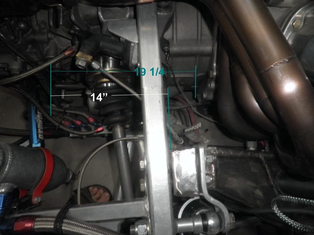
14" is at the curve of the mount.
3/4" thick is the pointy part. The mount bar section is 1" thick.
1" is all the lips.
I didn't include the positioning of the fiberglass piece. This will be governed by your clip, your vertical supports and the clips final position. Lots of ways to do it. I think that you position the clip to its final closed resting point with an engine lift then loosely attach all the pieces with clamps. Word to the wise, If you use a lift and cotton straps be careful if you go under the wheel wells. This will stress the fiberglass inward. Use a board the length of the width of the wells so that the board takes the inward stress. Mount the 6mm bar to the frame and adjust as needed. Mark all pieces where they seem to fit the best. Remove all and then attach them all together. The mounting bar bolts only go through the fiberglass mounting and not through the vertical supports unless you make this piece solid instead of hollow. This needs to be a tight fit to carry the load. There have been some interesting mounting pieces for the frame in other builds. You may want to search and take a look at those and see if those interest you. This is just basic stuff on mine. I use Nylocs and a bolt to allow the clip to be raised easily.

PB220168_zpscf24df45.jpg


33 1/4" is the outside measure of the link at the cross motor frame member.

PB220176_zps16e9565d.jpg


14 is the length from the vertical cross motor frame member mount to the end of the frame.
19 1/4" is the full length of the frame member.

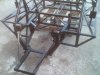
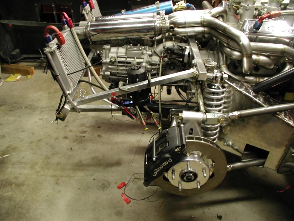
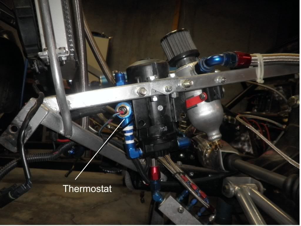
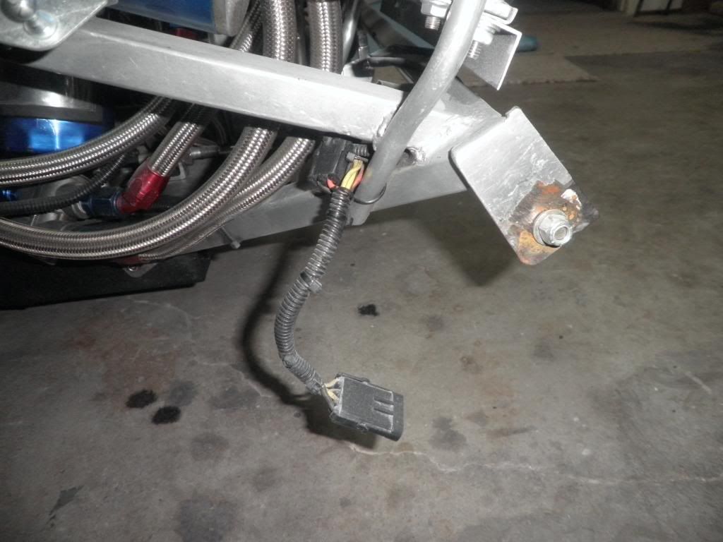
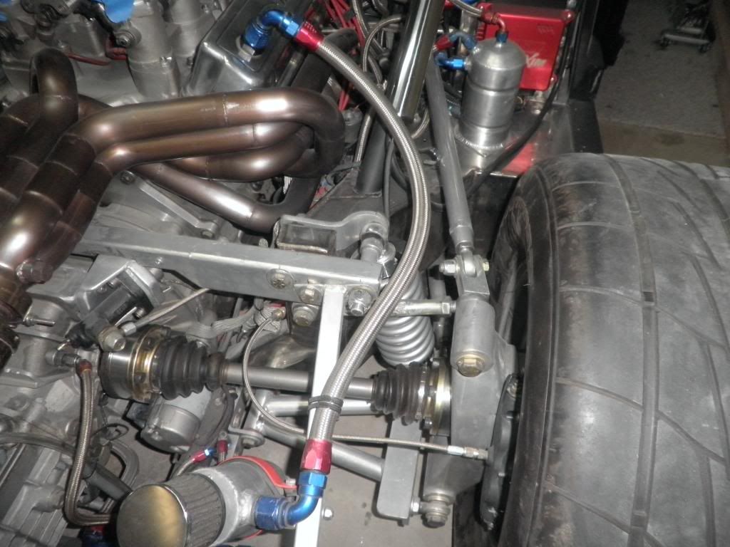
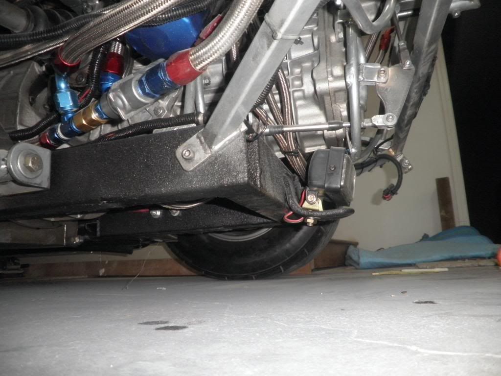
Here are some other shots to help you visualize the set up.

PB220173_zps3afe6aad.jpg


PB220169_zps899f2e07.jpg


PB220175_zpsb0b2a7e5.jpg
 
Last edited:
This is absolutely above and beyond Bill! Thank you very much. I'll study these and see what I can incorporate. Doing this part this week.

Darrin
 
Back
Top