Hi Ed don't cut panel around plate just fit panel over the top you will need to drill through panel and tap plate for door catch after body fit.
Regards Mick.
Regards Mick.

great thank youHi Ed don't cut panel around plate just fit panel over the top you will need to drill through panel and tap plate for door catch after body fit.
Regards Mick.
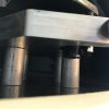
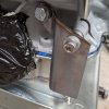
thanks i had almost committed haha lucky i didnt have the timeNo, that plate is got the door latch to mount to, it should be behind the alloy panel.

thanks you im happy how its turning out no big mess ups yet thankfullyYou may need to trim the top to get the body to fit but that's all, looking very nice
")
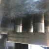
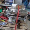
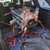
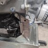
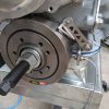
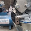
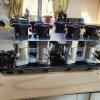
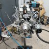
Thanks for the help might have a go as I have a bit off time on my hands and it's a long way from Cheshire to Southampton but that really helpful will save me a lot of messing about trying to figure it out hahaHi Ed, I went to Micks to get the body fitted, made life much easier. The rear clips bolt through the glass fiber panel with four bolts with large washers, Mick used different thickness of spacers to get the correct fitting of the rear deck before fitting. Pictures attached

Yep. Fitting the body is not easy.
The spider needs to be bolted down solidly at all four corners otherwise it will keep moving. The spiders are pretty floppy and can change shape if stored unsupported. If you just clamp it every little nudge will move it. You really need to fit some suspension and ensure that it is set at the same distance from the car centreline on both sides.These can then be used as reference points for centring the clips. Having the wheels fitted makes it much easier. Once the spider is bolted down solidly fit the front clip so it fits well to the spider and is the correct height at the front and rest it on a box with suitable packing. Then make up a piece of string with a weight on the end so it hangs vertically. set the string to the edge of the wheel arch and see where this plumb line meets the wheel or the the suspension. If the wheel arch is centred then the distance from the plumb line to the wheel or suspension will be the same on both sides. If it is not then the front of the spider is at an angle. remove the bolts at the front of the spider and slot the holes to alter the angle angle of the front of the spider and rebolt down in the new position. Replace the front clip and recheck that it is centred using the plumb line method. Repeat until the clip is centred. Check that the screen still fits OK.
Now place the rear clip on the car and adjust until it is a good fit to the rear of the spider and the correct height and rest it on a box with packers. Using the plumb lines check the centring of the rear clip by measuring the distance from the plumb line to the wheel or suspension on both sides. If it is the same then all is well. if it is different then unbolt the rear of the spider and slot the holes and rebolt down. repeat the plumb line process until the rear clip fits well t the spider and is centred with respect to the wheel or suspension ( and hence to the car centreline).
Mark or pin the final position of the spider so if it is removed it can be put back in exactly the same place.
Once the spider is correctly located and the clips placed and centred you can grovel underneath to locate the correct positions of the front pivot bar and the rear "parrots beaks". The parrots beaks can be placed in the bobbins and then the panel can be drilled for the bolts. The tubular spacers can then be made the correct length and then the parrots beaks cam her bolted to the panel.
Al this is much easier with one or two patient assistance who are willing to act as human clamps! I would assist having done a couple of them but as I am ancient I am locked away from Mr virus.
I will send you my mobile no. via email if you want me to explain a bit more.
Cheers
Mike
...but as I am ancient...
Ed Iv fitted my Spyder the same way as you so your not alone. Iv chosen to get the Spyder and screen fitting right and ill get the rest to fit one way or anotherThanks for the help have already mounted the rear clip and the back of the centre section just be taking measurements but sounds like your method would have been a better idea if I'm honest hopefully I have got it right