Chassis Alignment, Front, Camber and Ride Height
Much has been said about chassis tuning. There are many good posts. Dean Lampe wrote an excellent article published in Kit Car. For what it is worth, here is what we did.
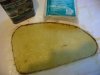
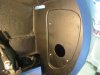
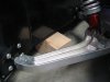
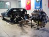
1. Ride height. Ride height must be established before one can tune the chassis. We made four blocks to set the ride height. Three short pieces of 2 x 4 to give us a block 4 ½” high. This then became the measurement for the front ride height. We did the same for the rear, but added a ½” piece, so the rear ride height would be 5”. When setting ride height, keep in mind that the car will settle a half inch or so, so add a little extra. To do the remaining chassis adjustments, we simply rest the chassis on the ride height blocks.
2. Remove the shock absorbers. It makes the rest of the job a lot easier.
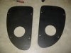
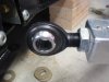
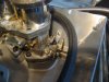
3 Lower control arm. The heim bolts need to be turned out six to eight threads from the lock nut, both fore and aft. When locating them within the mounting pockets, bias the lower control arm forward by placing three fourths of the washers aft of the heim bolt. This is necessary to assure the tire will clear the chassis and to establish the castor.
Getting those washers into place is a real challenge best accomplished with two people. We found it impossible to get an absolutely fight fit, since the gap remaining after the washers were all in place was too narrow for another washer, but loose enough that we could wiggle the washers a bit. To resolve this issue shims could be cut from thin aluminum, slid into place, and the tabs bent over to hold it.
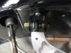
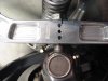
4. Upper control arm. Remove the lock nuts from the heim bolts. They are not necessary. One needs to get the upper control arms relatively close which the lock nuts prevent. We left about three threads exposed to set the camber. It is easier to adjust the camber with the top control arms since one does not have all those crazy washers to deal with as on the bottom control arms. We spaced the washers so that the upper control arm was centered.
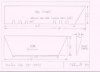
5. Check the camber with the lower control arm in the correct right height position. (4 ½” spacer under the outer end in our case). We settled on camber of about negative -.5 degrees, nearly neutral.
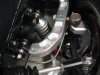
A digital level was used to check the camber. I know this is not the best method for measuring camber, but it seems to work pretty darn well. There comes a time when one just gets tired of having to buy new tools for every little issue. It was checked with the level in opposite positions to make sure the level was properly zeroed.
We checked the camber with the tires off against the brake rotor, and rechecked it with the tires on against the tires. The measurements were within a few tenths of a degree, which should be fine for street use. Note that the camber changes noticeably as ride height changes which is why the lower control arm and the chassis need to be set at proper ride height. Recheck the ride height after a few miles.
6. Castor is less critical. For steering that will tend to pull more to center, add castor. For less centering affect, less castor. The manner in which the lower control arm is positioned forward and the upper control arm centered will dictate the castor. To change it, move the upper control arm forward or aft. For now, we are going to leave it centered and see how it handles.
7. Toe was determined using the parallel strings, as described by Dean Lampe in his article. We settled on just a slight bit of toe in. Interestingly, one reference we saw for tuning a GT 40 recommends slight toe-out for the track and toe-in for the street.
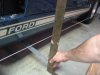
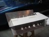
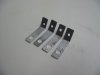
8. Using string as a reference point for chassis alignment requires that the string be perfectly parallel to the car. Knowing that the RCR chassis is remarkable square, we simply measured from the grove that holds the lower rocker panels in place. Four 16” long pieces of two inch wide aluminum were cut. These were slid in the grove that holds the lower rocker panels. A square was then pushed up against these four aluminum pieces and used as a reference for aligning the string. Admittedly this is not the most accurate way for aligning a chassis, but for road use it proved satisfactory.
Much has been said about chassis tuning. There are many good posts. Dean Lampe wrote an excellent article published in Kit Car. For what it is worth, here is what we did.
1. Ride height. Ride height must be established before one can tune the chassis. We made four blocks to set the ride height. Three short pieces of 2 x 4 to give us a block 4 ½” high. This then became the measurement for the front ride height. We did the same for the rear, but added a ½” piece, so the rear ride height would be 5”. When setting ride height, keep in mind that the car will settle a half inch or so, so add a little extra. To do the remaining chassis adjustments, we simply rest the chassis on the ride height blocks.
2. Remove the shock absorbers. It makes the rest of the job a lot easier.
3 Lower control arm. The heim bolts need to be turned out six to eight threads from the lock nut, both fore and aft. When locating them within the mounting pockets, bias the lower control arm forward by placing three fourths of the washers aft of the heim bolt. This is necessary to assure the tire will clear the chassis and to establish the castor.
Getting those washers into place is a real challenge best accomplished with two people. We found it impossible to get an absolutely fight fit, since the gap remaining after the washers were all in place was too narrow for another washer, but loose enough that we could wiggle the washers a bit. To resolve this issue shims could be cut from thin aluminum, slid into place, and the tabs bent over to hold it.
4. Upper control arm. Remove the lock nuts from the heim bolts. They are not necessary. One needs to get the upper control arms relatively close which the lock nuts prevent. We left about three threads exposed to set the camber. It is easier to adjust the camber with the top control arms since one does not have all those crazy washers to deal with as on the bottom control arms. We spaced the washers so that the upper control arm was centered.
5. Check the camber with the lower control arm in the correct right height position. (4 ½” spacer under the outer end in our case). We settled on camber of about negative -.5 degrees, nearly neutral.
A digital level was used to check the camber. I know this is not the best method for measuring camber, but it seems to work pretty darn well. There comes a time when one just gets tired of having to buy new tools for every little issue. It was checked with the level in opposite positions to make sure the level was properly zeroed.
We checked the camber with the tires off against the brake rotor, and rechecked it with the tires on against the tires. The measurements were within a few tenths of a degree, which should be fine for street use. Note that the camber changes noticeably as ride height changes which is why the lower control arm and the chassis need to be set at proper ride height. Recheck the ride height after a few miles.
6. Castor is less critical. For steering that will tend to pull more to center, add castor. For less centering affect, less castor. The manner in which the lower control arm is positioned forward and the upper control arm centered will dictate the castor. To change it, move the upper control arm forward or aft. For now, we are going to leave it centered and see how it handles.
7. Toe was determined using the parallel strings, as described by Dean Lampe in his article. We settled on just a slight bit of toe in. Interestingly, one reference we saw for tuning a GT 40 recommends slight toe-out for the track and toe-in for the street.
8. Using string as a reference point for chassis alignment requires that the string be perfectly parallel to the car. Knowing that the RCR chassis is remarkable square, we simply measured from the grove that holds the lower rocker panels in place. Four 16” long pieces of two inch wide aluminum were cut. These were slid in the grove that holds the lower rocker panels. A square was then pushed up against these four aluminum pieces and used as a reference for aligning the string. Admittedly this is not the most accurate way for aligning a chassis, but for road use it proved satisfactory.