Chuck and Ryan's RCR Build

Chuck

Supporter
Dashboard Insulation

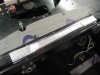
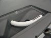
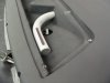
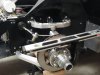
What happens when a plastic tube filled with cold air is surrounded by hot humid air? That is the situation under the dash since our Generation I AC system has its ducting just below the solar heated fiberglass dash. The AC works just fine, but there is a bit of condensation on really hot humid days that drips from the underside of the dash. While the dash was off the car a way to improve the situation was explored.

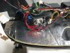
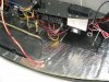
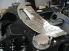
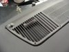
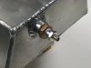
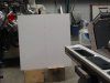
It was a simple matter to cut a fiberglass insulation blanket from Cool It to fit between the fiberglass dash and the duct. The center section of the blanket had to be cut out since the clearances are tight, so a section of adhesive foil backed insulation was cut to fit that exposed area. It is about a sixteenth of an inch thick so it will not interfere with the placement of the dash.

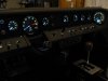
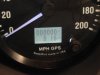
A generous opening was also cut in in the blanket in the area where the GPS antenna for the speedometer is located. The insulation will be secured to the underside of the fiberglass dash before the dash is installed.
 

Attachments

  • DashDuct6.JPG
    DashDuct6.JPG
    357.4 KB · Views: 649
  • DashDuct5.JPG
    DashDuct5.JPG
    349.2 KB · Views: 585
  • DashDuct3.JPG
    DashDuct3.JPG
    447.4 KB · Views: 590
  • DashDuct4.JPG
    DashDuct4.JPG
    470.6 KB · Views: 534

Randy V

Moderator-Admin
Staff member
Admin
Lifetime Supporter
Good idea Chuck!

How do you get air to the demister vents? I was planning on cutting a passage through to the HVAC plenum..
 

Chuck

Supporter
Good idea Chuck!

How do you get air to the demister vents? I was planning on cutting a passage through to the HVAC plenum..

Good Question!


After a lot of thought, we decided NOT to open a connection to the dash top vent. Here are the reasons:
1. On the original GT this was an outside air vent, through the front center opening on the clip.
2. Because of the size of the vent, any air entering would come out a relatively low velocity, making it ineffective as a defroster
3. The pressure of the air coming out of the side vents would be decreased.
4. When is the last time one drove the GT in freezing or rainy conditions where a defroster was necessary?

However, if we were to add a vent, here are some thoughts.
1. The back of the vent butts up directly to the HVAC plenum, so one could simply drill a hole through each and air would be diverted to the vent. Some foam tape between the HVAC plenum and the vent would effectively seal the connection
2. A tube, perhaps ¾” diameter, could be connected to this opening, curving toward the sides of the dash, and the end then plugged. A quarter inch slot about three inches long along the top of the tube would provide a narrow opening so the air exiting would be higher velocity, making it more effective as a defroster. A section of electrical conduit may work well. (See pictures attached)
3. Once the grill is put back in place, the tube would not be visible. (Assuming the tubes are painted a matching shade of black).
4. Air should exit only on the left and right sides based on the design of the grill.
 

Attachments

  • Defroster1.JPG
    Defroster1.JPG
    282.5 KB · Views: 564
  • Defroster2.JPG
    Defroster2.JPG
    297.3 KB · Views: 520
  • Defroster3.JPG
    Defroster3.JPG
    413.3 KB · Views: 554

Randy V

Moderator-Admin
Staff member
Admin
Lifetime Supporter
Your ingenuity amazes me at times... Great solution!

I was not worried so much about driving in freezing conditions as I was concerned with geting caught out in the rain and getting the windshield foggy. Certainly a case could be made for use of RainX anti-fog or just a polished application of dishsoap..

I had also thought it over about directing the center duct air to the demister, but there is precious little space between the scoop and the demister itself. Engineering a water trap to remove the majority of any rain encountered would be a sizeable task. So far, this is the only scoop or duct on my car that is nwot fully functional.. But I'm not done yet! :D

Thanks for the tip Chuck!
 

Chuck

Supporter
Gauges Illuminated

Powered up the gauges. The GPS speedometer got a fix in about 20 seconds. IN THE GARAGE. It accurately reported our altitude and the time – without having to set anything.

We hope to be ready to start the engine and drive it sans body within the next week or two. So close!
 

Attachments

  • DashInstall2.JPG
    DashInstall2.JPG
    265.7 KB · Views: 570
  • DashInstall3.JPG
    DashInstall3.JPG
    259.3 KB · Views: 547
  • DashInstall4.JPG
    DashInstall4.JPG
    251.2 KB · Views: 506
  • DashInstall1.JPG
    DashInstall1.JPG
    303.7 KB · Views: 497
Your ingenuity amazes me at times... Great solution!

I was not worried so much about driving in freezing conditions as I was concerned with geting caught out in the rain and getting the windshield foggy. Certainly a case could be made for use of RainX anti-fog or just a polished application of dishsoap..

I had also thought it over about directing the center duct air to the demister, but there is precious little space between the scoop and the demister itself. Engineering a water trap to remove the majority of any rain encountered would be a sizeable task. So far, this is the only scoop or duct on my car that is nwot fully functional.. But I'm not done yet! :D

Thanks for the tip Chuck!

Not to hijack Chucks build log. Randy you are right, i got caught more than once in rain and the windshield tend to fog up. I have not yet start up my AC, so i have to rely on the heater only.
If you check my build log you will see, that i have build a plenum out of the two reinforcing tubes below the chassis´s top plate, by closing them with an aluminium sheet to built a closed plenum. THe AC/heater unit simply is bolt to this plenum and the side vents connected to it with hoses. i simply have cut 2 x 1 inch holes on the top of this plenum exiting to the demister vent. When the dash is mounted it seal to this holes with the help of a 10mm foam stripe laid around this hole.Matching holes have been cut into the dash demister opening.
Velocity is plenty and it works great to defog the windscreen. Would not want to run the car without.
I realy can recommand my plenum solution. no hoses no nothing and you still have the reinforced chassis structure. Legroom is still plenty even with the AC/heater unit mounted lower 1 inch (du to the 1 inch square tube)

check out details here

http://www.gt40s.com/forum/gt40-build-logs/24525-toms-rcr-40-trackracer-17.html#post281008

TOM
 
Last edited:

Randy V

Moderator-Admin
Staff member
Admin
Lifetime Supporter
Chuck the gauges look fantastic.. I wish I had the gps version like you.

Thanks Tom.. I will post notes on your blog as I have some questions in that I have gone a different route with wiper motor etc.

Sorry for the thread drift Chuck!
 

Chuck

Supporter
Expansion Tank: Installation

Before installing the tank we wanted to check for leaks. An air fitting (Schrader valve) was temporarily placed in the 3/8” bung and the tank filled until one could hear air escaping from the radiator cap, which was around 15 pounds of pressure. It held pressure overnight.

Next the tank was filled with water and left sitting on the antique oak kitchen table overnight. This is a risky technique for leak testing, since a mechanical failure could incur a high degree of spousal wrath. Fortunately the table was dry the next morning.

The tank has a capacity of one gallon; four times more than the Canton it replaces.

The tank was installed after attaching two mounting tabs. Rubber spacers separate the tank from the fire wall. The tank was positioned so that the top of the neck is the highest point in the cooling system.

The coolant tubes which were fabricated from stainless tubing when we originally built the car had to be modified slightly in order to fit the tubes between the engine and the tank. About two inches were trimmed from the lower portion of the “U” shaped section that connects the lower and upper hoses. The section that connects to the thermostat was also shortened an inch.

The neck of the expansion tank is positioned so that it is the high point in the system. The top including the cap interferes slightly with a small section on the back side of the clip, so a small area was trimmed away to provide clearance. This is not a weight bearing section.

The recovery tank was connected despite the increased capacity of the expansion tank. It is just a bit of added protection.
 

Attachments

  • ExpansionTankPressure.JPG
    ExpansionTankPressure.JPG
    256.4 KB · Views: 497
  • ExpansionTankCompleteI.JPG
    ExpansionTankCompleteI.JPG
    356.7 KB · Views: 526
  • ExpansionTankCompleteE.JPG
    ExpansionTankCompleteE.JPG
    393.1 KB · Views: 569

Chuck

Supporter
Bill

Not an issue. The header is about a half inch away from the coolant tube. Probably hard to tell in the pics.

As previously configured the two were just barely kissing each other. Both tubes are stainless. Other than a bit of discoloration on the coolant tube it was never an issue. When we did this rebuild a bit more attention was paid to clearances. So they are not kissing anymore.

The real clearance issue will be the headers aft of the weber carbs. The fuel line is nearly touching. Now that is an issue that will need to be resolved.
 

Chuck

Supporter
Suspension

The stock suspension was okay for street driving, but with shocks and springs that made the GT felt softer that we liked, it was time for a change. Fran recommended QA1 shocks and springs. We settled on the following spring rates:

Front: QA1 DS-303 shock. 7-650 Spring.
Rear: QA1 DS-501 shock. 9-500 Spring.

Yes the front shocks are 150 pounds stiffer than the rears. Tom Schwab’s posts, among others, use that set up. Jac Mac explained it well: The lower front shock is mounted inward from the ball joint, thus the spring moves a lesser distance than the rear for the same amount of vertical tire movement. Thus to achieve a comparable spring response one needs a stiffer spring on the front. It is simple geometry, but never occurred to me until I read some posts on this web site.

The rear springs set near the top end of the threaded section on the shocks making it difficult to get enough height. Adding one inch extensions was a simple solution. (QA1 9004-110). Using a ten inch instead of a nine inch spring would not have been a good idea because the clearance at the bottom end is very tight. The extension keeps the lower spring adjusting nuts an inch higher which helps with the clearance

Bump stops from QA1 were also added. (QA1 BC02). It is doubtful they will ever be needed, unless we go airborne and come down really hard. But it is easier to add them now with the shocks are off the car than later.

We have several extra springs and they are not that expensive, so we may do some experimenting. In addition, the adjustable shocks have a wide range of ‘stiffness’ settings from soft to hard which will help adjust the ride.

When reassembling the suspension, the steel components prone to rust were cleaned and given a light coat of Eastwood Detail Gray color. It blends well and looks natural.

While the front rotors were off they were turned by our local tire shop to eliminate a slight bit of pulsation noticed under light braking.

The bolts were torqued per the specs and then locations marked with a Sharpie.

It will be a while before we can get out on the road to see how the new set up works.
 

Attachments

  • SuspensionFront1.JPG
    SuspensionFront1.JPG
    317.4 KB · Views: 510
  • SuspensionFront4.JPG
    SuspensionFront4.JPG
    358.2 KB · Views: 481
  • SuspensionRear4.JPG
    SuspensionRear4.JPG
    349.8 KB · Views: 499
  • SuspensionShockSetting.JPG
    SuspensionShockSetting.JPG
    367.2 KB · Views: 565

Chuck

Supporter
First Start

1. Coolant, a total of five gallons mixed, was used. But we did something different. The Schrader valve (air filler) on the expansion tank, used to make sure there were no leaks, was left in place. When the expansion tank was filled to the brim with coolant the cap was put on and the system pressurized until coolant and air bled from the cap (about 15 pounds of pressure). The cap was removed and the coolant level was noted to be near the bottom of the tank. It was refilled and the process repeated. In all we did this about a half dozen times before compressing the system would not change the level. (Of course the bleeder valve on the radiator was also opened, but don't open it much when the pressure is applied.) The last time we pressurized the system we walked away and left it until the following day. The hiss of air when the cap was opened 24 hours later confirmed there were no leaks.

Satisfied that the system had been purged as well as possible, the Schrader valve was removed from the expansion tank and the port properly plugged.

2. About four gallons of fuel were poured into each tank. Interestingly, the two gauges showed well over a half tank with just four gallons or so. But the shape of the tanks is such that half a tank of fuel by volume will register more than half full. We also noticed that the gauges did not register at all until there was well over a gallon of fuel in the tank which is due to the sender being at least a half inch from the bottom of the tank. That means there is a gallon or two of fuel remaining when the gauge shows empty: a nice reserve.

3. The fuel filters between the tank and the input side of the fuel pumps were replaced with glass filters. Something about a glass case filter just does not seem right, but the anti slosh foam in the fuel tanks is known to deteriorate after five years or more. The glass filters will enable us to know if and when this becomes an issue. (There is a second, much larger, filter/water separator between the pumps and the carburetor.)

4. The engine was cranked over a bit until the oil pressure started to register with the ignition off. When the left fuel pump was flipped on the pressure registered just under 3 pounds on the gauge (I suspect Jim Inglese set the regulator that came with the carbs). A couple of blips of the throttle, fuel squirted into the carbs. Ignition. It started immediately. Oil pressure came up smartly to 60 pounds. After just a few moments the engine was idling smoothly. I am always amazed how the Weber carbs can idle so well without a choke on a cold engine. The carbs were easily balanced. The timing set at 32 degrees. We let it run until the coolant came up to operating temperature and we could tell that the thermostat had opened.

Mechanically the GT is now essentially complete. Now the cosmetic details need to be addressed, suspension adjusted, and body installed. So close !
 

Attachments

  • ExpansionTankCompleteF.JPG
    ExpansionTankCompleteF.JPG
    416.4 KB · Views: 535
  • FuelFilterGlass.JPG
    FuelFilterGlass.JPG
    320.9 KB · Views: 551
  • Weber3.JPG
    Weber3.JPG
    405.2 KB · Views: 556
Gauges Illuminated

Powered up the gauges. The GPS speedometer got a fix in about 20 seconds. IN THE GARAGE. It accurately reported our altitude and the time – without having to set anything.

We hope to be ready to start the engine and drive it sans body within the next week or two. So close!
Hi , you guys are doing anincrediblejob on your car! I really like the tach and speedo! would you be able to give me info and part numbers for them , I would like to put those 2 in my CAV, thanks and have a merry christmas, all the best, Neville Nesbitt.:laugh:
 

Chuck

Supporter
Neville

Call the folks at Speed Hut. Tell them you want the legacy series speedometer, GPS version, and tachometer.

Next tell the that the font, numbering, lettering, should be the same as what is used on the Kirkam gauges. Be sure to explain clearly what the "red line" should look like. Ask for black dial / white font (reverse blue glow).

You can specify most anything you like, except a trademark (like "Smith").

They will e mail you a proof to confirm the order.

There is no specific model number, per se. They custom make the face per your specs.

I ended up talking with Andrew Westberg, who was very knowledgeable.

If you buy a full set of gauges a discount may apply. Also note they run promotions from time to time.
 
Hi Chuck

Great work on the rebuild, just one thing in the second picture you are using a glass inline filter, are they near any heat, some have used these
in the cobra engine bays and they have broken and the cars have gone up
in flames, Andy :uneasy:
 

Chuck

Supporter
Hi Chuck

Great work on the rebuild, just one thing in the second picture you are using a glass inline filter, are they near any heat, some have used these
in the cobra engine bays and they have broken and the cars have gone up
in flames, Andy :uneasy:

Good point. They are located behind the "wings" that create a space between the passenger compartment and engine compartment on either side. The pic I posted was taken through the access opening. When buttoned up it will be completely isolated, so they will be well shielded from heat.

I have some trepidation about using glass filters but in this protected location should be fine.
 
Chuck

my reco is to use aeromotive inline filters. They have great flowrates and if connected with AN fittings are quick to remove and to check. Also their stainless filter mesh is washable and reusable. Don´t risk anything with your precious car.

merry christmas to you and your Family

TOM
 
:thumbsup:
Neville

Call the folks at Speed Hut. Tell them you want the legacy series speedometer, GPS version, and tachometer.

Next tell the that the font, numbering, lettering, should be the same as what is used on the Kirkam gauges. Be sure to explain clearly what the "red line" should look like. Ask for black dial / white font (reverse blue glow).

You can specify most anything you like, except a trademark (like "Smith").

They will e mail you a proof to confirm the order.

There is no specific model number, per se. They custom make the face per your specs.

I ended up talking with Andrew Westberg, who was very knowledgeable.

If you buy a full set of gauges a discount may apply. Also note they run promotions from time to time.
HI, thanks for the info, all the best, Neville.:thumbsup:
 

Chuck

Supporter
Bump steer

With the GT on jack stands and the shocks and springs removed, it was a good opportunity to see if our bump steer was adjusted properly. We sought a simple way to check it without spending a bunch on special tools. Precision measurements were not important, as long as we could determine with reasonable accuracy what adjustments were needed to tune out any bump steer.

The tools needed: a laser level (with magnets for attachment to metal surfaces), jack, and a piece of poster board. A vertical line was drawn on the poster board which was positioned a few feet in front of the wheel. The distance does not really matter, as long as you can see the laser dot. The laser level was attached to the brake rotor with its magnets and the laser beam pointed forward.

The lower A arm was positioned in its normal ride height position with the jack (typically approximately level). The poster board was moved so that the laser beam lined up with the vertical line. A horizontal line drawn on the poster board marks the starting reference point.

Now raise the jack about an inch or more. If the laser stays on the line or moves just slightly inward, there is no bump steer or slight inward toe with bump. Not bad. Now lower the jack stand below the ‘neutral’ position marked on the board. I had a tiny bit of outward movement of the laser beam, meaning toe out. But toe out on jounce is of less concern than toe in on bump. Consider what Carroll Smith said in his book Tune to Win, page 62:

"I described the geometric causes of bump steer and detailed the procedures used in adjusting it in Prepare to Win, which means that if you don’t have a copy, you will now have to buy one. At that time I basically stated that the front bump steer should be adjusted to as close to zero toe change as could be arranged but that toe-out in bump should be avoided at all costs. (emphasis added)"

One can move the spacers on the bump steer kit to fine tune the bump steer. Since the alignment can be visualized on the poster board, one can easily tune out the bump steer without any fancy equipment. I am sure that there are better ways to measure bump steer, but I doubt there are any less expensive. (Someone will point out that the camber will cause the beam to divert inward slightly on bounce and outward on jounce. True. If one plans to seriously race the car, I don’t think a carpenters level and poster board will be the tools of choice.)
 

Attachments

  • BumpSteer1.JPG
    BumpSteer1.JPG
    251 KB · Views: 459
  • BumpSteer2.JPG
    BumpSteer2.JPG
    361.8 KB · Views: 466
Back
Top