Chuck's Jaguar D Type Build

Jag Lovers is an excellent site also.I did a 62 etype and found that site invaluable. Lots of great archives and Jag lovers eager to help.There were also a couple of Dtypes being built and a couple finished and driven.LOTS of Jag knowledge.

If it were me Id use both sites.Keep your friends here and make some new ones.Im sure they would be glad to see you there also. Thanks DJ
 

Chuck

Supporter
Thanks for the tip DJ. I will check it out.

I started a parallel blog at JaguarForum.com, but quickly reached a limit on the number of pictures that could be posted. That limitation made use of the forum untenable. Unfortunate, really, since there were some pretty good folks frequenting the site.
 
This is a fantastic thread, and I love D-types almost as much as GT40s. But since it’s an RCR car, why not put it in the dedicated RCR forum, along with the other oh-so-cool products Fran makes?
 

Chuck

Supporter
Rear Suspension, Part III, Secondary A Frame

The primary A arm on the original D Type provided lateral alignment of the rear suspension. RCR uses an A Frame following the same concept as the original but bolts the apex of the A frame directly to the differential housing.

DSC_0630.JPG


The original used a different method of attachment to the axle, adding a secondary A frame. We opted to duplicate the original concept. So the first thing we needed to do was come up with a suitable design.

A preliminary mock up was made using available high tech materials: blue masking tape, welding rod, and cardboard.


DSC_0333.JPG


Once the high tech mock up seemed workable, a bit of on line research followed to find workable parts. We settled on a spherical bearing as the connection point since it would assure proper motion as the axle moved up and down as it passed over the growing potholes that dominate our local roadways. Then it was time to draw up the plans and come up with a parts list.

The parts total around $120.

(1) Narrow spherical bearing for 1 5/8” bolt. Pegasus 3071-10
(1) Spherical bearing weld cup. Pegasus 1825-150-1187
(2) Chromoly Rod End for 5/8”. Summit PFN-REXMR10
(2) Tube end, weldable, 5/8”. Summit FKB-2107
(2) Clevis brackets, to weld to differential axle tubes. RCR.
(2) 1” OD Chromoly, .083 wall thickness, trim to length
Now the fun part. Construction.
 

Chuck

Supporter
Rear Suspension, Part III, Secondary A Frame

Jigs. We like jigs. It keeps things in their proper position while being built and enables multiple copies to be made that will, hopefully, be exactly the same. So a jig was fabricated from a nice scrap of birch veneer plywood. High tech. This jig serves not one but two functions. First it provides a means of exactly locating the clevis brackets on the axle tubes. Second, it provides a means of assuring the parts are tack welded in the proper position.

DSC_0512.JPG


A drill press with a tubing cutter attachment was used to fashion the rounded ends of the chromoly that mate with the spherical bearing cup. The heim joint was used to assure all was tight before it was tack welded. Once tack welded it was removed from the jig for final welding.

DSC_0515.JPG


DSC_0516.JPG


The same jig assured the exact placement of the clevis brackets on the differential. The differential was flipped upside down and the brackets tack welded in place, after which the jig was removed so final welding could be completed later.

DSC_0523.JPG


Tack welding complete, the secondary A frame was test fitted. Thanks to the jig, it fit perfectly.


DSC_0526.JPG


With the axle temporarily connected to the tub, the secondary A frame and the RCR supplied primary A frame were connected and the axle moved through ranges of travel to confirm this design would work. Final welding and painting can now be completed.

DSC_0529.JPG


Chuck

Supporter
Rear Suspension, Part V, Primary A Frame

Once the replacement secondary A frame was fabricated we decided to revise the primary A frame as well. The engineers in the crowd may have noticed that the bolt holding the secondary A frame to the primary A frame is in single shear, which is usually not a good thing where lateral forces are involved. That is, however, exactly the how the original D Type was built. A bit of research revealed that a 5/8” grade 8 bolt has estimated shear strength in excess of 21,000 pounds. I doubt the fact it is single shear will be an issue.

Nonetheless we decided to modify the design of the RCR primary A frame to eliminate the ‘stub’ at the apex and make it more closely resemble the original.

A jig was set up to assure it would be dimensionally exact. It was tack welded on the jig, then removed and finish welded.

DSC_0659.JPG


The difference in the RCR design and our design is apparent in this photo. RCR used a heim joint to connect the A frame to the differential. Our design uses a 5/8” bolt through a spherical bearing to connect the primary A frame to the secondary A frame.

IMG_2310.jpg


A pair of spacers was added on either side of the spherical bearing to assure proper clearance as the suspension moved through its range of travel.

DSC_0699.JPG


Measurements confirmed four inches of travel up and down from normal ride height, which should be more than adequate for the potholed plagued roadways.

DSC_0689.JPG
 
Before you get too excited about paint, jump up & down on the pinion and check for flex in your 'new' secondary 'A' frame, Im pretty sure your going to have to add a bracket from the lower rear diff cover bolts to the pivot point once you feed some engine torque into that. Left as is the first time you feed some power into it the pinion will want to climb upwards.
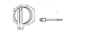
EDIT: Ive attached a dwg of a rear cover Ive used before on OZ Ford Falcon rear axles that spend time on dirt ovals. These cars factory have an alloy rear cover with pivot pin for a watts linkage that does not like gettin hit hard. By using the A-frame as per dwg we got a lower rear roll center plus a setup that was longer lasting. Rear cover is fabbed from 6mm plate and the Bolt is made from HT bar to replace that large bolt you have, The bolt uses a nyloc nut and is free to rotate in the A frame, the bolt that attaches the long 'bolt' to the cover goes thru a sleeve in the large end so it is can be tight, but sleeve allows the A-frame to move up n down as reqd. Overbuilt, yes and unlikely you need to make it as heavy. By making the A-frame swing radius longer it also makes the pinion angle change less thru the range of movement which makes life easier on the rear u-joint of driveshaft.
 

Attachments

  • Untitled-4.png
    Untitled-4.png
    28 KB · Views: 428
Last edited:

Chuck

Supporter
Jac

Good to hear from you and really appreciate your input and advice.

The two A frames are there only to prevent lateral movement, functioning as a panhard rod. The A frames will not prevent rotational motion of the axle, as you have correctly noted. Not clearly visible in the pictures recently posted are the four trailing links which should prevent any rotation or longitudinal motion of the axle. I can stand on the pinion input shaft and there is no rotation of the axle.

I can see what you are proposing would be a good option, likely more stable than the original D Type design. If we have an issue with the trailing links not preventing rotation adequately we could pursue that option.

I appreciate your alerting us to the issue and we will definitely check for aberrant motion when we fire it up, a long long time from now. If I am missing something don't hesitate to let me know. Thanks.
 
Hi Chuck, Yes I did not see the lower pair of trailing links. I would still suggest that you disconnect the coil overs and then with A-frames and 4 link all fitted that you move the axle assy thru its full range of movement, especially roll, as sometimes with a 4 trailing link setup in roll you will get a bind situation at the extremes of movement that will eventually cause a failure. while I think its unlikely in your car since total wheel movement is likely to be no more than say 4'' each way (8" total). Easy to check it now. In some saloon race cars Ive had to resort to a single rubber rod end to replace one of the heim joints to give a bit of compliance.
 

Chuck

Supporter
Jac:

Did exactly what you suggested when I was working on the design. I am not at home and thus don't have access to the pictures showing 8" of travel, 4" bounce and 4" jounce, on each side separately and total. It worked great with no binding. When I next have access to the pictures I will post some test photos.

Actually in one of the posted pictures above there is a tiny blue tape with and arrow and the words "4 ride height". That was taken with the suspension four inches above ride height. The gap between the jack stands and axle is apparent as the jack stands were set at normal ride height.

Regarding the use of a rubber rod end to replace a heim, you are spot on. The original D type used some sort of rubber bushing between the connections between the primary A frame and the chassis. Ours moved easily through the range of motion noted, so we will stick with heim joint connections.

Thanks for your good advice.
 

Chuck

Supporter
Rear Suspension, Differential

Inspection of the differential revealed that the input shaft did not rotate evenly. Over .040 of ‘wobble’ was measured. We needed an excuse to upgrade to a limited slip differential, and this provided the excuse.

Differential work is not for the faint of heart. Precise alignment, proper spacing, backlash and preload are critical. It is hard to believe that something as simple in concept can be so complicated in execution. There are a host of You Tube videos, some very good and many not. Ford also has a set of directions on line for replacement of the ring and pinion gear which is very detailed and will give some insight as to the complexity of this project.

https://performanceparts.ford.com/download/instructionsheets/FordInstShtM-4209-8.pdf

Opening the case of the 8.8 differential revealed an unexpected surprise. LSD! (If you are a child of the sixties, not that LSD). Replacement of the open differential with a limited slip would have cost around $500 for the parts. This discovery was welcome news.

IMG_2412.jpg


So we could stop right here and move on. Anyone building an RCR D Type will now know it comes with a limited slip and there is no need to open up the differential. But for those curious about this saga, we will continue.

Discovery of the limited slip did not answer the question about why the input shaft wobbled. So we proceeded to take the differential apart. First the pin in the center of the carrier is removed, then the two axles, then the carrier. We were pleased to see that all of the bearings, pinion gear and ring gear were new. The yellow paint for checking alignment was still visible on the ring gear. So it had been rebuilt, just not rebuilt correctly.

The nut holding the pinion gear in place must be carefully installed with a specific preload. For new bearings it is 16 – 28 inch pounds per the Ford specifications. This is critical. When we checked it after removing the carrier there was NO preload. In other words, someone forgot to set the preload. The pinion gear was essentially loose. Now we know why it ‘wobbled’.


IMG_2470.jpg


The pattern of the yellow paint on the gears was incorrect, further confirming improper assembly.

If you made it this far, the question arises: why not check the preload before taking the dang thing apart? Good question. But the preload has to be checked before the carrier is installed and puts drag on the pinion gear. So, we really had no choice.

While we had it apart, a fresh coat of Eastwood chassis primer and paint was applied, to dress up the axle.

Three lessons: First, it is critically important that everything be inspected. Never assume it is right because it is already assembled. Second, we now know we have a limited slip differential. Finally, we finished the job that the axle rebuilder started and are satisfied that it has been done correctly.

IMG_2569.jpg


Randy V

Moderator-Admin
Staff member
Admin
Lifetime Supporter
With no preload and slop on the pinion shaft - putting 10 miles on that ring and pinion would have destroyed them....
 

Chuck

Supporter
With no preload and slop on the pinion shaft - putting 10 miles on that ring and pinion would have destroyed them....

Yes, pretty amazing that a ‘professionally’ rebuilt differential had such an obvious flaw.

The moral of the story is we got to check everything and start with the premise it was not done correct until proven otherwise.
 

Chuck

Supporter
Aluminum body

The original D Type was built like the World War II aircraft that Jaguar’s engineers and craftsmen had designed and built a decade before; aluminum monocoque construction held together with thousands of rivets. How cool would it be to build an aluminum bodied reproduction?

Fran informed me that Race Car Replicas is planning to provide an aluminum body that will dimensionally match and be an option to the fiberglass body. This was great news, since given the option, I would opt for an aluminum body. Ryan and I visited the site where that project is taking place to see for ourselves.

Manufacturing the original aluminum body was a labor intensive time consuming project. Aluminum panels were formed using an English wheel and then placed on a wooden buck for more forming after which they were gas welded together. The cost of producing an aluminum body today using construction practices followed more than a half century ago would obviously be prohibitive. So a different technique is being pursued.

Like the original multiple panels are being fabricated and welded together. But instead of being hand formed with an English wheel they are being pressed with “tools” that produce the panels in minutes instead of hours. These panels are then welded together and finished so that the seams will effectively disappear. The goal is to produce a beautiful aluminum body at an affordable price as an option to the fiberglass body.

This project is in its early stages. When we visited several test panels had been fabricated and set on a fiberglass body. It will take some more time to complete the first prototype and until then details, like cost, will not be known.


IMG_2807.jpg
 

Chuck

Supporter
Front Clip, Inner Panels

We ordered our D Type without the inner panels installed. The plan was to learn some composite construction techniques that we had not previously pursued. My expectation is that RCR will sell the cars with the head light boxes fabricated from aluminum, so the following discussion will not be pertinent to most builders.

Preliminary work on the light boxes was started. These provide the primary structural support for the front bonnet and the attachment points to the chassis. A strong, precise, structure is needed. The first step was creating patterns which proved to be a time consuming task.

The bonnet was leveled resting upside down. The aft flat sections behind the wheel openings were used as the location to level the bonnet fore and aft. A board placed cross wise was used to level it laterally. This revealed a bit of a twist, so the weight of brake rotors was used to help get everything lined up.

99472


99473


Once it was leveled the center lined was determined and marked with a black Sharpie. Next, using the vertical level, lines were drawn to mark the expected joint between the headlight box panels and the underside of the front clip.

99474


99475


All of this time-consuming work is to assure that the head light boxes are properly fit. Patterns were made from poster board, then more precise ones from foam core board. (Foam core board is about 3/16” thick and is more rigid, thus better for the final patterns). We were striving for a snug fit with less than an eighth inch of space around the perimeter.

There are three critical angles. First, the surface of the lateral sections are exactly vertical, which is why we went to such lengths to level the chassis. Second, the inner vertical edge of each lateral section is vertical to assure that the two forward longitudinal sections will also be vertical. Finally the two sections are joined at a ninety degree angle, checked with a carpenter’s square.

99476


99477


With the foam core board patterns cut, fabrication of the panels is next.
 

Chuck

Supporter
Front Clip, Composite Construction

When building aircraft it is called composite construction, not fiberglass, even though the materials used are essentially the same. Composite construction sounds more sophisticated. Since the D Type is a sophisticated vehicle, the following will discuss the composite construction of the light box panels.

The materials used were purchased from Aircraft Spruce, and as the name of the supplier would imply, are intended for airplane use. The West system hardener and resin with their convenient pumps make mixing a breeze. The process proved to be simple and straight forward. There were no nasty odors.

Quarter inch thick foam panels are cut to shape. (Last-A-Foam 6 lb). The fiberglass cloth is placed over it on both sides. (BID Fiberglass RA7725). The clip hinge connection points were reinforced with a total of three layers of cloth on each side. Peel ply (2 oz Nylon Release Ply) was pressed on the final coat of to assure a smooth texture when it was dry. The result was amazingly rigid, smooth panels that fit well.

99930


99931


99932


99933


The completed panels were set aside for installation at a later time when we get back to the body work. In the meantime we are getting back to work on the chassis, which should be a bit more interesting than cutting patterns and fabricating composite panels.
 
Back
Top