Dan's Build

Day 410

Purchased the 90 degree hinges. Working the tail to cover the hole for the Graz and to make the area around the hinges and street tail bottom bigger to hide the necessary slots cut into the tail.<?xml:namespace prefix = "o" ns = "urn:schemas-microsoft-com<img src=" /><o:p></o:p>

Modified the mounting bar to beef up the heim joint attachment bar by replacing the nut with a threaded tube. <o:p></o:p>
 

Attachments

  • DSC02768.jpg
    DSC02768.jpg
    207.9 KB · Views: 415
  • DSC02780.jpg
    DSC02780.jpg
    119.5 KB · Views: 434
Been focused on clean up the last week or so.

1. Straightened out the exhaust and added muffler hangers
2. Adapted the 90 hinges to transfer the street tail wing to the frame (copied Mikes approach and added my own twist). Note the U clamp on the top of the hinge to add support as well as the stop to hold the rotating bracket.
3. Prototyping the tail scoops to direct air into the air filter box (not yet built).
4. Glassed in the revised lower tail section, primed, blocked and ready for paint.
5. Added fuel to the fuel system. Pressure check is next.
6. Re-primed the engine. added the fuel inlet tubes to the tank (not clamped yet) which required me to adjust some heater hoses. Getting ready to hit the start button for the first time.
 

Attachments

  • DSC02803.jpg
    DSC02803.jpg
    102.5 KB · Views: 477
  • DSC02789.jpg
    DSC02789.jpg
    216.1 KB · Views: 644
  • DSC02791.jpg
    DSC02791.jpg
    149.2 KB · Views: 454
  • IMG_1117.jpg
    IMG_1117.jpg
    146 KB · Views: 428
  • IMG_1157.jpg
    IMG_1157.jpg
    123.1 KB · Views: 463
Big day today

We had engine start. A few systems leaks to clean up.

Infinity one start is a bit touchy and doesn't start every time. Touching throttle pedal prior to a start seems to helps, not sure why. Any Ideas?

GM MIL light is on at fuse box but OBD2 (tech2 compatible??) reader shows no codes. A power cycle turns light off but comes back on once started.
 
Congratulations!!!! That had to feel good. Until you actually build one of these, you have no appreciation of the many things that could go wrong if not done properly. Great Job!
 
I had a bad hose on one radiator section. Replaced it and all is good. Some of the fuel line AN fittings were not tight enough, nothing a wrench could not fix.

So a few more SS brake line fittings to tighten and the major systems are leak free (fingers crossed).

Have yet to fill the AC system , but expect a few leaks there to be consistent.

Hearing the engine fire up for the first time was incredible. It remotivates you to reach that finish line......
 
Day 501

I thought I would share with the new builders a perspective that I know I did not have going into wiring and alignment. This is my opinion which may vary from others, but it’s what I experienced during these two phases.

1. During the wiring phase, I elected to abandoned the factory instrumentation and purchased gauges which were non-digital (I like gauges that I can see relative needle location aka aircraft style). Anyway, this change made me take a hard look at differing wire connection styles. In the attached photo, there are two basic styles that I used, Weather Tech and Delphi. The Weather Tech are physically larger and easy enough to work with, however, I found that the male pins had a propensity to deform at times while being plugged into the female side of the plug. On the other hand, I really liked the Delphi GT 150 and 280 series connectors (other side of picture). The differences in the 150 and 280 series are the pin sizes hence the AMP loads. The 150 series is smaller (aka instrument panel stuff) and the 280 has larger pins for bigger loads. I found that the connectors had more pin quantity variety (aka 2 up to 10 or more pins). This made it possible to design more flexibility into my harness. It is the builder’s choice, but I really found the Delphi (and there are other brands with similar features), a better choice and merits your consideration.

2. As for alignment, it really starts the moment you put your suspension parts back on the frame. To achieve the camber (~1 degree), caster (5-6 degrees) and tow (1/16) for a street machine, I would suggest you set your inside heim joints with about 4 threads showing outside the nut. I discovered that the outside top A arm heim, gave me 1/10 a degree change in camber for a full rotation of the heim. I set my system on the ground by using two vinyl tile with grease between them, placed this under each tire so the suspension could move as I adjusted it. I accepted the caster settings preset by the factory which ended up around 5.5 to 6 degrees. I take my caster measure with a little grain of salt, as I lacked the precision needed to measure the caster, but it was close. As for tow, I used the string method and adjusted the front and back to achieve 1/16-inch toe. There are a lot of variations on how to achieve the rough alignment, but this is the technique I used and it’s not far off. I will eventually have it professionally aligned, but this gives me enough confidence to get the body aligned.

Set the Aeromotive fuel controller today to hold the 60 PSI needed for the LS3. Nearly drove it for the first time, but needed to reset the shifter cables so I ran out of time. Tail section about to come home to measure for the verticals to mount the wing on my street tail. The fuel gauges I am using give me the capability to manually program the gauge to the fuel tank sender for both empty and full so it’s not limited to any preset OHM reading generated by common fuel sending units.

Still having a minor issue with a two brake line leaks. If I remove the stainless lines, I will go to NiCopp lines in lieu of stainless. NiCopp is used by the European car manufactures and is easier to form, flare and seal and is reported to have similar anti-corrosion properties as stainless.

Other builders have different experiences and perhaps a more refined approach, so take this update only as my approach to solving my issues.
 

Attachments

  • DSC02811.jpg
    DSC02811.jpg
    119.3 KB · Views: 363
  • DSC02812.jpg
    DSC02812.jpg
    171.1 KB · Views: 358
  • DSC02813.jpg
    DSC02813.jpg
    144 KB · Views: 379
Hey Dan. You did the alignment part a touch backwards. You must first locate square, parallel, track and wheel base. First is making sure the frame mounting points are correct. You were able to get each corner relative to itself, but you don't know if your track is offset, or parallel. Or, if wb is exact each side. So basically, your car could still crab without doing the full process.

Basically to do this, you will be creating a large rectangle, with an X in the middle for your measurements. With chassis lifted, you will be using a plumb bob to transfer the mounting point locations to the ground, and put some tape on the floor, and mark position of mounting points on chassis. Based on marks, measure for equal wb, equal track (based on centerline), then square with diagonal measurements. If that all checks out, then proceed to installing the lower control arms with spacers side to side, and depth of the rod end equal (unless you had to correct for anything in your previous chassis measurements).
Now, with lower control arms installed, set them at 0 degree angle. This is how you want to set them to measure again. This time, you will be using a consistent position near end of control arms ( I use ball joint zerk fittings if equal, or ball joint centerline for measuring) and repeating your square, and parallel measurements a second time. If all checks out, then you are ready to install uppers, and use then you can use your basic alignment procedure to set uppers. If you cannot get the uppers in the correct position, then you will need to move the lower. If you move one lower, you must move them all, or you loose you previous squareness.

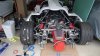
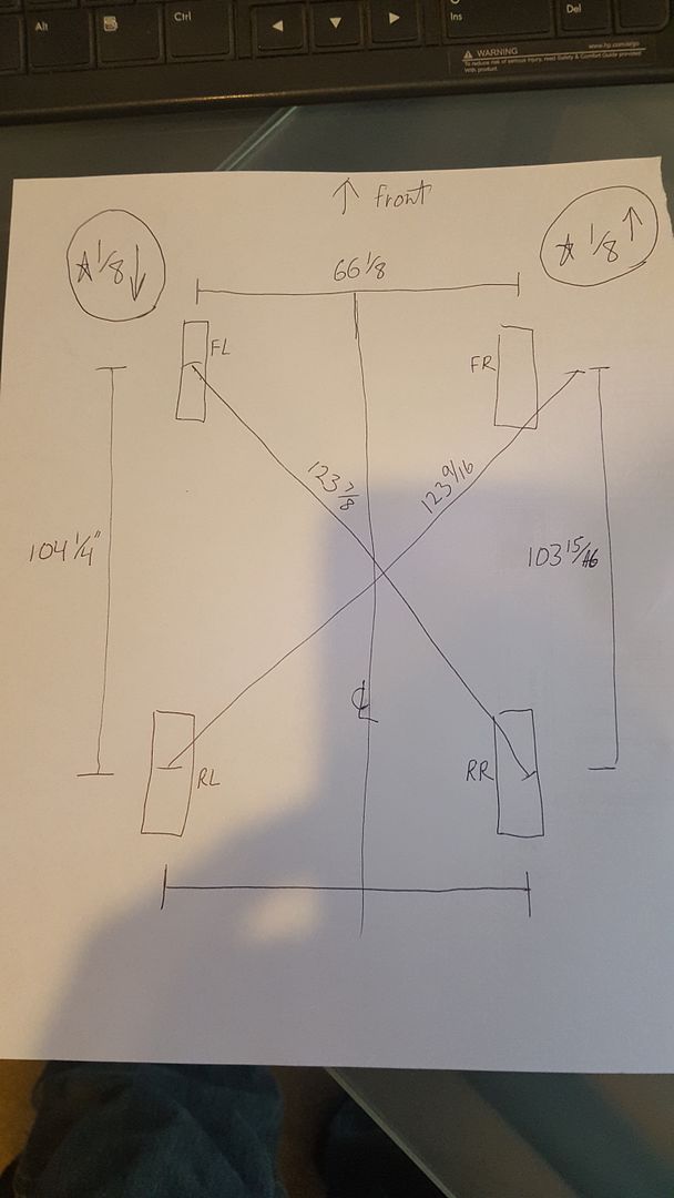
Here is a pic of the measurements from my car, using the ball joint measurements. My suspension was already on car, and this process done, but there is corrections to be made as they didn't correct wb parallels.
You can see, to make my car square, the front left needs to be moved forward 1/8", and front right needs to be moved back 1/8". That will equal out all of my measurements and the wheel placement based on bodywork, shows that this exact move, will center both fronts in the openings.
I don't have all of the measurements in there, but it will give you an idea of how to set up the measuring grid and the measurements to take. I will still be fully disassembling my car, and will start the process from step one upon reassembly. I just wanted a baseline initially to show if there were any major problems.

 
Also, for your torque check marks, extending the mark to the stationary surface will give you the ability to do quick visual checks on movement, like this-

final33.jpg
 
Scott

Thanks for the responses. I plan to remark critical torque bolts as suggested.

Any idea what the engineering tolerances are for the chassis?
 
Far tighter than an oem that I can assure you
With every corner being independently adjustable you can get the set up absolutely spot on !!
 
Far tighter than an oem that I can assure you
With every corner being independently adjustable you can get the set up absolutely spot on !!

I have to agree - I've checked the chassis all over; rear engine box, suspension pick up points, vehicle centerline, passenger compartment, foot box - everything is square and equal left to right, at least within the thickness of my laser's beam and the printing on my tape measure.
 

Howard Jones

Supporter
Ya me too. My stripped chassis was so close to square than I couldn't see any variance. I would say less than 1/32. Then once the suspension was on I held that to 1/32 again.

Unless the chassis wasn't held to tolerance on the welding fixture then yours is going to be fine. Don't freak out. You can do a quick check by using a steel tape measure and doing a cross check from the front corners of the foot box to the rear corners of the chassis members in a cross pattern. Do it on the bottom of the car. LF to RR should equal RF to LR. If you can't see any difference with the exception of your measuring then you are fine. You don't need to take it apart to do this and give yourself some piece of mind. This is the same thing as Scotts more precise plumb bob and tape marks on the floor method.

Remember that you can adjust the suspension to correct a lot so a quick check to less than 1/4 inch should be just fine so you can get a good nights sleep but again don't be surprised if yours is dead square like mine.

Putting the body on a square chassis/suspension is critical. Then make the fiberglass fit and you will end up with a perfect alinement and no body or tire interference. This is your first and most important priority. It's not very sexy or a whole lot of fun but I assure you fixing it after the fact is nightmare.
 
I think my terminology may have gotten in the way of my question. The welded aluminum chassis is fine, very well built.

My question is based on Scotts measurement of the suspension arms etc. I measured mine and as it sits I have slightly less than 1/2 inch to correct on space between front to rear "tires" to square up the suspension.

So let me re-ask.........what is an acceptable tolerance fore to aft and cross to cross measures to ensure the suspension is set square.....1/32, 1/16, 1/8, 1/4 ??????
 
Dan
The control arms are all CNC machined and there's absolutely no way that they are different lengths
All the brackets are CNC laser cut , again no way they have large size discrepancies
 
Nothing to worry about on parts, guess I'm just not explaining this well. In Scotts post above 231 he shows a drawing on the measures I'm duplicating.

Based on getting the car square, zero differences is perfect, but nothing is perfect. is there a measurable delta between Scotts measures that is unacceptable.

I can't seem to get the lower A arm to adjust as the cup holding the lower A arm will not come lose (4 bolts) I'm afraid I'll strip out the bolts.

:huh:
 
You cannot adjust anything inside the rear most lower front control arm pocket
That is the fixed zero point from which the suspension needs to be set
 
Back
Top