Has anybody on this site checked out www.emachineshop.com? I've heard some very good things about the site from others. It's a great concept: you download their software, design the parts that you need, specify materials, and you can play around with different designs, materials and quantities and price the parts instantly. I'm told the products delivered were first rate.
So let me explain how I used emachineshop (EMS) software to come up with a design for rear anti-roll bar brackets for my Roaring Forties kit. Since I have increased the rear tire width from 255 to 315, the increased track width will probably cause the car to understeer. The fix will be a rear anti-roll bar. THe first order of businedd will be to locate a part of the suspension where I can attach the lower links from the anti-roll bar. I don't like the way CAV does it because it would require me to weld a tab onto my lower control arms, which would cause a bending moment about the heim joint. Let's take a look at my RF's rear suspension so I can show you what my plan is.

The above picture is of the rear part of my lower rear upright. This is the only suspension link on the car that's in single shear and I don't like that. My fix will be to fabricate a bracket that will box in the heim joint, converting the single-shear mount to a double-shear mount. The bracket will attach to the upright at the two (unused) holes, as well as at the pivot bolt that goes through the upright. The upper surface of the bracket will be where the anti-roll bar end links attach. If I locate this attachment point immediately above the heim joint, there will be no bending moment put on the suspension by the anti-roll bar. So this bracket gives me a good ARB end link mounting location and it improves the single-shear pivot bolt by turning it into a double-shear mount. Note that, since the lower arm geometry will not change, I'll also need to fabricate a thinner inner bushing to accomodate the thickness of the metal bracket.

The picture above is the front part of the lower rear upright on my RF. Note the shiny plate that attaches to the upright. It serves to locate the lower drag link as well as the lower damper mount. Robert Logan at RF was kind enough to share a drawing of that plate with me, and it serves as the basis for my rear anti-roll bar bracket design.
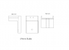
So the first thing I did was download the EMS software and draw RF's damper mount plate. Here it is modeled as a 3-mm plate (the part RF provides is 5 mm):

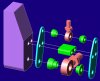
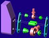
Next, I designed the reduced-height bushing which I'll need to accomodate the 3 mm thickness of the bracket. Here's a picture of the bushing, followed by the rendered model of the smaller bushing:


more to come...
So let me explain how I used emachineshop (EMS) software to come up with a design for rear anti-roll bar brackets for my Roaring Forties kit. Since I have increased the rear tire width from 255 to 315, the increased track width will probably cause the car to understeer. The fix will be a rear anti-roll bar. THe first order of businedd will be to locate a part of the suspension where I can attach the lower links from the anti-roll bar. I don't like the way CAV does it because it would require me to weld a tab onto my lower control arms, which would cause a bending moment about the heim joint. Let's take a look at my RF's rear suspension so I can show you what my plan is.
The above picture is of the rear part of my lower rear upright. This is the only suspension link on the car that's in single shear and I don't like that. My fix will be to fabricate a bracket that will box in the heim joint, converting the single-shear mount to a double-shear mount. The bracket will attach to the upright at the two (unused) holes, as well as at the pivot bolt that goes through the upright. The upper surface of the bracket will be where the anti-roll bar end links attach. If I locate this attachment point immediately above the heim joint, there will be no bending moment put on the suspension by the anti-roll bar. So this bracket gives me a good ARB end link mounting location and it improves the single-shear pivot bolt by turning it into a double-shear mount. Note that, since the lower arm geometry will not change, I'll also need to fabricate a thinner inner bushing to accomodate the thickness of the metal bracket.
The picture above is the front part of the lower rear upright on my RF. Note the shiny plate that attaches to the upright. It serves to locate the lower drag link as well as the lower damper mount. Robert Logan at RF was kind enough to share a drawing of that plate with me, and it serves as the basis for my rear anti-roll bar bracket design.
So the first thing I did was download the EMS software and draw RF's damper mount plate. Here it is modeled as a 3-mm plate (the part RF provides is 5 mm):
Next, I designed the reduced-height bushing which I'll need to accomodate the 3 mm thickness of the bracket. Here's a picture of the bushing, followed by the rendered model of the smaller bushing:
more to come...