Drawing

Ellis Hubbard

Lifetime Supporter
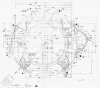
Can someone furnish me a drawing with the hole locations dimensions on the surface between the block and bell housing ?
 

Doc Watson

Lifetime Supporter
if its a 302 or 351......
 

Attachments

  • SVOCylBlockF&RView.jpg
    SVOCylBlockF&RView.jpg
    146.5 KB · Views: 742
newbe question from someone that wasn't around when these things were racing.

Based on the bell housing drawing, should i conclude that these cars were built using imperial bolts and threads? standard 60 degree and not Whitworth 55 degree threads or metric?

Thanks for the drawings as well. added to my archives.

Ryan
 

Randy V

Moderator-Admin
Staff member
Admin
Lifetime Supporter
I think that since the engine blocks of the day were all SAE / Imperial threads - it would be a valid assumption..
At least I've never heard of an iron block Ford that had anything else..
 
I Have just read this old post and I think Ryan has raised an interesting point. The cars built in England did they use UN or Whitworth fasteners?
Given that UNC and Whitworth effective thread diameter are so close makes them interchangeable other than 1/2". All engine and mechanical components made in USA would have been UNC or UNF at 60° and Whitworth 55°. I have seen Whitworth bolts come lose in UNC threads so How did they over come this in the day?
Woody
Having worked in a Ford w/shop thru the sixties IIRC you will find even the UK fords converted or were UNC/UNF during the early sixties. The MKIV V6 engines used 1/2" bolts in heads & main caps and I think a service letter had some data advising the problems if we used any BSW stuff. The German car stuff was metric and IIRC the Ford Cortina ~ 1972 was the first UK body to use metrics, but the 1600cc x-flow pushrod remained UNC/UNF, but trans & diff were metric, along with the 2000 OHC pinto & 2.3 thru 2.8 German V6... however many of our old semi redundant BSW sockets now fitted most of the metric bolts.
So the GT40's were probably no real problem apart from the Collotti & ZF being metric. The T44 appears to be all UNC/UNF from data I have gathered.
 
It's ugly, but here's a scan of the original MK2 bell housing top view.

Bob, I have just superimposed that image over the bell housing bolt positions for the Windsor block. None of the bolt holes seem to line up.

I have know idea about the big block for engines, did they run a different bell housing pattern?

Presumably the two lower chassis mounts on that bell housing are still in the same position as the Windsor block stuff.
Ryan.
 
jac mac, I'm trying to locate the positions for the two lower bell housing mounts onto the chassis.

Regards Ryan
 
From my data pile on bell housing , 10.16" apart & 5.16" below crankshaft centerline.
Might be a bit of error on that height. This is T44, ZF may be different and apparently the aftermarket USA stuff does not bother.
 
That's the same measurements that are in that picture jac mac.
If the T44's were fitted to the FE engined MK II's would they have had a higher crank shaft centre line than the 289?
Ie does the bell housing for the 289 have the chassis tabs in the same spot? Or was there a chassis difference in this area for the MK II and the chassis mounts are in a completely different spot?

Just pondering a few of the other original design decisions as well.
It looks like the rear clip mounting structure needed to be un bolted to take the lower wishbones out? If that's the case why didn't they use the same size fasteners on all the joints to make it quicker under race conditions if they needed to remove this part?

Gets you thinking doesn't it!
Keep well.

Ryan
 
Lateral thought process here... as the T44 uses a generous hypoid R&P offset which enables the input shaft to run much closer to the axle centerline than the ZF or ZFQ there would be no need to change that height dimension, add to that by looking at the dry sump pan of the FE it has a noticeable front to rear rake which means the engine sat more nose high than the SBF installations, this would be to gain more clearance between ring gear & road as for some reason they stuck with the Ford Factory dia rather than taking the clever route of reduced dia on the SBF by the english folk.
 
I will need to take that in for a bit Jac mac. Lots to consider. Are there any drawings showing the overall size of the T44? Similar to the common drawing showing installation dimensions for the ZF 5DS25?
 
Back
Top