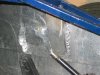
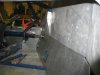
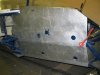
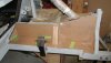
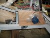
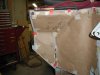
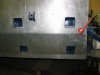
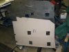
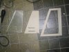
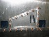
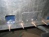
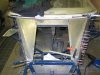
Frank's KVA Build

some pics from the panneling
 

Attachments

  • IMG_2921 (Small).jpg
    IMG_2921 (Small).jpg
    46.1 KB · Views: 376
  • IMG_2922 (Small).jpg
    IMG_2922 (Small).jpg
    54 KB · Views: 349
  • IMG_2923 (Small).jpg
    IMG_2923 (Small).jpg
    42.9 KB · Views: 359
Frank,
I know how frustrating the paneling can be. I tried several techniques including cardboard from old boxes to brown wrapping paper. The brown wrapping paper that comes on rolls is best. Find it in the Christmas wrapping section. The paper lets you know about the subtle bends that may be required, especially in the front wheel wells. Once cut out and trimmed to the dimension you want, tape it to the frame. Add any remarks you need to make sure it is correct, then trace it onto the aluminum sheets(stainless in my case) with a felt marker and put any notes on the sheets to remind you of the issues in that area. Use either a nibbler or plasma cutter to cut it out. Then just trim as needed and either weld or use the trusty rivets. If you use the rivets, add some caulk behind them to keep them from rattling if they work loose. Here are some of the panels I did with my car. Depending on how involved you want to get, the eventual layout will give you the right way to cut it out. Some can be rather complex and you have to add a little length for the bends. Cut a little larger or longer and trim back. If you need plans for a builder, I can supply you with a low cost idea that I used. Mostly angle iron and a work bench.

Bill
 

Attachments

  • P1010032.jpg
    P1010032.jpg
    32 KB · Views: 367
  • P1010034.jpg
    P1010034.jpg
    49.1 KB · Views: 382
  • P1010044.jpg
    P1010044.jpg
    37.4 KB · Views: 366
  • P1010105.jpg
    P1010105.jpg
    42.8 KB · Views: 423
  • P1010108.jpg
    P1010108.jpg
    62.7 KB · Views: 427
Bill,
I use cardboard what they use for making passapatoe's (the ring around a painting)
it's hard and about the same thickness as the alu and easy to cut for bends

I've got a plumbers chears (for cutting ) and a plumbers foulding bench see pictures.
And for some corners i use the welder i started this week with welding alu it's hard but with practise.......
And after welding i grind it off and looks like as if it's one piece.
But still a much work

Frank
 

Attachments

  • IMG_2924 (Small).jpg
    IMG_2924 (Small).jpg
    36.6 KB · Views: 310
  • IMG_2925 (Small).jpg
    IMG_2925 (Small).jpg
    55.7 KB · Views: 321
  • IMG_2926 (Small).jpg
    IMG_2926 (Small).jpg
    57.3 KB · Views: 332
  • IMG_2927 (Small).jpg
    IMG_2927 (Small).jpg
    39 KB · Views: 329
  • IMG_2928 (Small).jpg
    IMG_2928 (Small).jpg
    54.7 KB · Views: 335
more pictures
 

Attachments

  • IMG_2929 (Small).jpg
    IMG_2929 (Small).jpg
    51.9 KB · Views: 337
  • IMG_2930 (Small).jpg
    IMG_2930 (Small).jpg
    46.5 KB · Views: 332
  • IMG_2931 (Small).jpg
    IMG_2931 (Small).jpg
    51.2 KB · Views: 346
  • IMG_2932 (Small).jpg
    IMG_2932 (Small).jpg
    59.4 KB · Views: 338
  • IMG_2933 (Small).jpg
    IMG_2933 (Small).jpg
    39.2 KB · Views: 323
  • IMG_2934 (Small).jpg
    IMG_2934 (Small).jpg
    50.6 KB · Views: 309
Re: frank's kva

I assume you are trying to eliminate any bump steer.

Bump Steer is when your wheels steer themselves without input from the steering wheel. The undesirable steering is caused by bumps in the track interacting with improper length or angle of your suspension and steering linkages.

As the car passes over a bump in the road the change in suspension height of the front wheel can cause the wheel to 'steer' in or out depending on the geometry of your suspension.

The perfect position for the steering rack and tie rod length will result in no 'steering' effect of the front wheels when the suspension is compressed or extended (unloaded), this is known as zero bump steer.

(Sorry this is where it gets a little technical......the picture will help...)

In order to accomplish zero bump the tie rod must fall between an imaginary line that runs from the upper ball joint through the lower ball joint and an imaginary line that runs through the upper a-arm pivot and the lower control arm pivot. In addition, the centerline of the tie rod must intersect with the instant center created by the upper a-arm and the lower control arm.

The instant center is an imaginary point that is created by drawing a line from the upper a-arm ball joint through the a-arm pivot where it is intersected by an imaginary line that extends from the lower ball joint through the inner control arm pivot. Where the two imaginary lines intersect is the instant center.

To achieve zero bump the front end must be designed correctly. The tie rod must travel on the same arc as the suspension when the car goes through travel. Simply matching lengths and arcs to prevent any unwanted steering of the front tires.

To exaggerate, if the tie rod were only 10" long and the suspension were 20" long then when the suspension traveled the tie rod angle would shorten much quicker than the suspension arc. In this scenario the tie rod would shorten much quicker through travel than the suspension and the car would toe in drastically over bumps. The shorter arc of the tie rod would pull on the spindle and toe it in through travel.


To prepare your car for bump steer.....

Your front suspension must be complete and set for racetrack conditions before you can measure the bump steer. All components must be tight and in proper position, a quality bump steer gauge is advisable to set up the suspension.

1
Set the car at ride height.

2
Use the proper size tires and air pressures.

3
Caster must be set.

4
Camber must be set.

5
Toe in must be set.

6
Tie rod lengths must be set.

7
Steering should be centered (tie rod ends centered on inner pivot points lower ball joints).

8
Steering must be locked down.

9
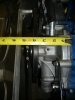
Measure from the ground to the lower ball joint or other reliable reference point. Write the number down.

10
Remove springs and disconnect the sway bar (if you have one).

11
Return the suspension to the proper height by using your reference number to the ground.

12
Bolt on the bump steer plate to the hub. Level the plate and note where the dial indicator is on the bump steer plate so that you can quickly return to the correct ride height.

13
Jack the suspension through 2"-3" of both compression and rebound travel and write down your results.

14
Shim as needed (see below)


Making Bump Steer Corrections

Now that you have measured your bump steer you will need to adjust, shim or relocate the suspension components to get the exact reading that you desire.


Symptom 1. Toes out in compression and in on rebound all in one direction. Cure 1. Decrease shim on outer tie rod or lower the inner tie rod.

Symptom 2. Toes in on compression and out in rebound all in one direction. Cure 2. More shim at outer tie rod or raise the inner tie rod.

Symptom 3. Always toes in both compression and rebound. Cure 3. Lengthen the tie rod as it is too short.

Symptom 4. Always toes out on compression and rebound.
Cure 4. Shorten tie rod as it is too long.

Symptom 5. Toes out on compression, then in on rebound and then starts back towards out with more rebound travel.
Cure 5. Less shim at outer tie rod and shorten tie rod.

Symptom 6. Toes in on compression, then moves out on rebound and then starts back towards in with more rebound travel.
Cure 6. More shim at outer tie rod and lengthen tie rod.

I hope this makes sense... and it really does need a bump steer gauge to do it accuratly.

Extract from...
Bump Steer

Hope this helps

Just stumbled on this write up, it is great for getting an understanding what it is that you need to do.

There was a piece that I couldn't get a grip on.

All measurements are taken with the steering "locked" in the straight ahead position. Does the desired geometry remain as the steering wheel is turned?

If not, does that mean the bump steer cannot be eliminated once the wheel is turned?

Otherwords, if the location of the tie rod ends are in perfect position (for straight ahead steering wheel) bump steer is eliminated for any steering angle?

Please forgive my ignorance on this, but I have the desire to learn. :thumbsup:
 
It's always if you turn the steeringwheel the geometry changes you can't chance that because of the position change of the steeringrod balljoint but bumpsteer is the most dangerous when you least expect it (on a straight with 120 of so miles)

frank
(that's my look at the fact's please correct me if i'm wrong )
 
My friend from the states is over and brought me some goodies.
Only my waterpump looks a bit far inside the car it´s the edelbrock 8841 i hope it´s going to fit.
And he brought me a set of cleko´s
it´s a super tool when you´re working with panels.

Frank
 

Attachments

  • IMG_2935 (Small).JPG
    IMG_2935 (Small).JPG
    41.7 KB · Views: 324
  • IMG_2939 (Small).JPG
    IMG_2939 (Small).JPG
    48.3 KB · Views: 339
  • IMG_2940 (Small).JPG
    IMG_2940 (Small).JPG
    52.5 KB · Views: 323
  • IMG_2941 (Small).JPG
    IMG_2941 (Small).JPG
    59.4 KB · Views: 361
Frank,
Thaose cleckos are a life saver when you start pulling those rivits. Hope you have a pneumatic puller, or you will start looking like Popeye. Your water pump is not that far into the cabin. You can make a bump in the cover. Mine, after moving the engine forward, came all the way under my elbow. So I took the whole thing off and went with an electric pump mounted remotely. Merziere and Moroso make good ones. You might look around for the short water pump. there are some threads about them on here somewhere.

Bill
 
I came across some of the shorty pics. Don't know if they will help.

Bill
 

Attachments

  • shorty water pump2.jpg
    shorty water pump2.jpg
    25.8 KB · Views: 354
  • shorty water pump serpintine.JPG
    shorty water pump serpintine.JPG
    119.1 KB · Views: 381
After living together for about 8,5 years ,I decided to keep her .:)
Last thursday it was the big day.......We got married
So now it's legal
 

Attachments

  • S5002638 (Small).jpg
    S5002638 (Small).jpg
    47.1 KB · Views: 425
  • S5002640 (Small).JPG
    S5002640 (Small).JPG
    55.1 KB · Views: 319

Bill Hara

Old Hand
GT40s Supporter
Congratulations Frank

Great to see you have a supportive wife - or was it a condition of marriage that you get to keep the GT40? :)
 
Thank you all
Luckely my wife is very supportif (mentaly),so i'm a lucky man.
I think that you can't start such a project if you don't have supportive partner (unless you want to be/stay bachelor).
So just a little good word for our undestanding wives/partners

Frank
 
Back
Top