The guy not having the engine ended up a blessing. The next day I had to to a small machine shop we have make some of our brake dyno parts at work. Over the years I have become friends with the owner. I noticed he had a Bridgeport mill with the table off it. So I asked what he was doing with the machine. He said they had taken it apart so they could grind the table and he was going to put it back together and sell it. I asked how much? He said if you put it back together $500.00. I said sold. I have been wanting a drill press for the garage or a small mill but for the money I'll have a real machine. So now I found another guy that has a engine block. Now I just have to ask my wifey for a small loan:thumbsup:

You are using an out of date browser. It may not display this or other websites correctly.
You should upgrade or use an alternative browser.
You should upgrade or use an alternative browser.
Good bye Locost 7 Hello GT40!!
- Thread starter RacerDave
- Start date
Dave;
Get that bridgeport fired up and make some parts. I have a J head machine and I use it almost every day. Did you happen to get any tooling along with the machine?
Usually the biggest issue is moving the machine, and supplying 3 phase power unless the motor has been changed.
Good luck
Phil
Get that bridgeport fired up and make some parts. I have a J head machine and I use it almost every day. Did you happen to get any tooling along with the machine?
Usually the biggest issue is moving the machine, and supplying 3 phase power unless the motor has been changed.
Good luck
Phil
Phil:
I was going through a couple of boxes that came with it last night. There were some R8 collets that is about it. I have a 5c collet fixture. Hold downs are cheap. I am going to use a rotary phase converter. When I had my machine shop in Michigan I ran the whole shop off a 25 horse rotary converter. Hmmm Parts I need to make Shifter, fuel tanks, door hinges, guide pins, latches ,rotor hats, demister grill.
I was going through a couple of boxes that came with it last night. There were some R8 collets that is about it. I have a 5c collet fixture. Hold downs are cheap. I am going to use a rotary phase converter. When I had my machine shop in Michigan I ran the whole shop off a 25 horse rotary converter. Hmmm Parts I need to make Shifter, fuel tanks, door hinges, guide pins, latches ,rotor hats, demister grill.
It has been a while since I have posted. I have been making a little progress and will post some photos in s few days.
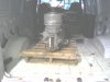
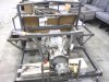
My garage at home has finally gotten to a usable state. So I am in the process of moving my bridgeport mill to its new home. Due to the lack of a forklift in the neighborhood. I had the machine taken apart to make the move easier.
My garage at home has finally gotten to a usable state. So I am in the process of moving my bridgeport mill to its new home. Due to the lack of a forklift in the neighborhood. I had the machine taken apart to make the move easier.
Attachments
Been making a bit of progress on the chassis. Made a card board template of fuel tank. It seems to fit well, I still have to check fit with side pod cover on. The transaxle mounts are progressing and the rear upper cross member with shock mounts is taking shape.
Attachments
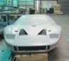
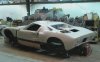
Hey I could not resist any longer. I picked up my body work last Saturday. Unloaded it Monday morning. Here it is Wednesday I just had to sit in the car. epper:epper:epper: I am very Happy with my body work. My tail section has the early MK I double tail light configuration. Well worth the wait Thanks Bill
P.S I had spectators so no engine noises or squealing tires:laugh:
epper:epper:epper: I am very Happy with my body work. My tail section has the early MK I double tail light configuration. Well worth the wait Thanks Bill P.S I had spectators so no engine noises or squealing tires:laugh:
Attachments

Hi All:
Had a very productive day today. I have spent very few weekends working on my build so far. I had gotten to a point that I had to have the nose and tail to continue on. Hence that is why I have been making the cardboard templates. Really If I had it to do again I would buy the body complete first. But Hind sight is 20/20 as they say. Back a couple months ago I noticed that my doors would not hinge into the area where they should on the chassis. I had just bought a cheap sawsall so I cut my dash bars loose and raised it about 1" figuring I had made it too short for the door to swing inward. So it looked like it would cure my problem. So I figured I would wait to double check it with the nose when it arrived and I did not weld it back in place. With the nose trimmed a bit and set in place the dash was to high about 1". So the height was correct. But the door will not swing inward. They hit the 1" tubing I had welded in place. So I welded the dash back in the orignal location. I had to trim the 1" tubing off that was in the way and constructed the door pockets out of sheet steel.
I also had to trim the corners of the dash because they hit the inner supports on my nose. But ran out of time to repair that today. Also some adjustments were needed to make the naca ducts that bring in fresh air in a workable way.
Attachments
![cp1_0822091533[1].jpg](/data/attachments/31/31450-665ad4ac931dc89dbc0d02c94eb9a0ae.jpg?hash=ZlrUrJMdyJ)
![cp1_0822091532a[1].jpg](/data/attachments/31/31451-6f574419f3c291bd99381c7383855ca8.jpg?hash=b1dEGfPCkb)
It has been almost a month since I posted last time seems to fly.
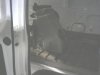
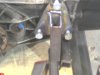
Have gotten some things accomplished in the last few weeks. The pedal box is painted and assembled. I ebayed the wilwood masters that I used for mock up and installed the AP short master cylinders I am going to use.
I installed the bottom part rear chassis bulkhead. I also had to move part of the dash bars near the fuel caps to clear supports inside the nose.
I have been waiting on the machine shop for bushings to make my control arm fixtures. I started building those today.
Will try to post pics tomorrow.
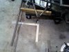
It has been a couple weekend in row where nothing has got in the way of working on the GT on Saturday. . Last weekend the contol arm fixture was the main project. As well as tacking together a lower control arm.
During the week I was able to confirm the right location for the front suspension.
Suspension location in relation to the body and because the chassis is tapered on the front has been a major hurdle for me. I ended up within a 1/2" of when I had figured it would be. Pretty close for no blue prints!!!!!
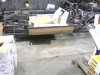
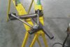
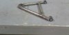
So with the location confirmed I built two lower control arms. Using Sleeves from Stock car products and bushings from Speedway motors
The ball joints came from Port city racing which are screw in chrysler K772 I think. The shock and sway bar mounts still have to be fabbed but here are the photos
I want to thank Frank B, Phil and Russ for all the help and advice.
During the week I was able to confirm the right location for the front suspension.
Suspension location in relation to the body and because the chassis is tapered on the front has been a major hurdle for me. I ended up within a 1/2" of when I had figured it would be. Pretty close for no blue prints!!!!!
So with the location confirmed I built two lower control arms. Using Sleeves from Stock car products and bushings from Speedway motors
The ball joints came from Port city racing which are screw in chrysler K772 I think. The shock and sway bar mounts still have to be fabbed but here are the photos
I want to thank Frank B, Phil and Russ for all the help and advice.
Attachments
Dave its looking good !!
Frank
Frank
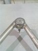
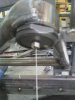
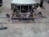
Over last weekend I made a bit more progress on the front suspension. I had the lower control arm mounts clamped in approximate mounting position. When I started building the chassis. The drivers side frame rail and the front nose bar were used as the datums on which the chassis was squared. So in order to make sure that I had the control arms in the correct location. I used grease zerk fittings to make plumb line holders in order to use plumb bobs verify measurements. I then clamped a bar to the nose bar and hung 4 plumb bobs to get the correct measurments.
So with all measurments double checked I put some good strong tack welds on the mounting brackets.
Also my rack and pinion arrived It is a Mustang II manual unit
So with all measurments double checked I put some good strong tack welds on the mounting brackets.
Also my rack and pinion arrived It is a Mustang II manual unit
Attachments
Hi Dave,
On welding the lower arms...
I'd was told that welding the fitting that the ball joint would be welded into would distort it enough to stuff up the press fit. Hence I machined them undersize and am now getting them bored to the right size for fitting (currently in progress).
I guess looking at the way these parts are sold for stock car racers the distortion cant really be an issue can it? otherwise the sleeves sold for the job won't work?
Think I've answered my own question there, but did you see distortion as an issue?
Thanks,
Hi Doug:
I used the screw in chrysler ball joints and sleeves. You are correct weld in sleeves shrink. Usually the short track stock car lowers are only welded about 1/2 way around the circumfrence of the sleeve. They weld the tube to the sleeve and then a strut tab to the sleeve. Which the strut gives you the triangulation strength. I know at Port city Racing and Coleman racing products we never re machined. If I were to make my own press in sleeves I would do it the way you are.
Also We always put a couple 1/4" tack welds on the ball joint to the sleeve as extra insurance. Vibration on a stock car chassis is a major issue.
Last edited: