
You are using an out of date browser. It may not display this or other websites correctly.
You should upgrade or use an alternative browser.
You should upgrade or use an alternative browser.
GT-Forte GTs40 build
- Thread starter fastdruid
- Start date
Thanks Marko. My time spent on it per "session" has dropped massively but it all adds up. Trouble is at an hour a day I don't really have enough to be worth an update and I keep thinking "I've not done much" then I look back at photos taken ~4 months ago and I've done loads.
So, more progress.
Firstly, tank straps (as I went and took a photo), these pivot at the bottom, bolt into the side rail at the top and then take a bolt through the middle to pull the tank tight.

(Middle ones aren't a "pair" they just happened to be the top ones in the pile!)
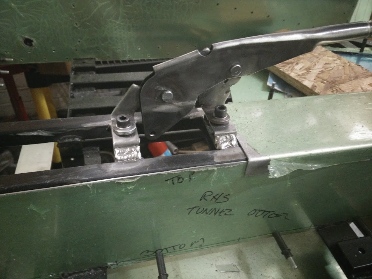
Handbrake mounts welded in
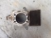
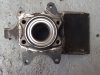
Adapters for the Audi rear bearings.

It looks not flush btw as there is a chamfer to allow good penetration when welding (as you can actually see with the second one which is resting to the right of the photo). Although I'll probably trim them some more round the edge.
Next job is making the front uprights.
Previously I'd bought a s/h set of the hub bearings I was planning to use cheaply so that I could cut them up and use them for mounting. Unfortunately my only method of cutting an accurate 84mm hole is in the lathe (oh to have a CNC milling machine!) and there isn't enough clearance to have a chuck and then an adaptor and then the upright even with the gap bed piece removed. Anyway I still needed the hubs for hole location etc so cut them up, removed the bearings and surfaced one side.
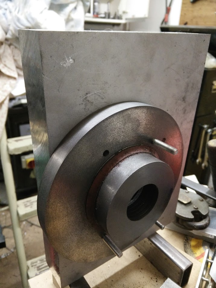
So to hold things securely I bought a new faceplate blank, faced, bored and threaded it. Then surfaced it off. It just happened that my large flanging tool fit perfectly in the cut down hub. So held in place with the tailstock and using my special M12 fine thread adaptor I punched location holes into the faceplate.

Then it's drill holes in the faceplate and the upright blank.

The holes in the upright blank btw were created by first centre-punching through a 1:1 scale printout of the model and then drilling them through.
It is an awesome technique. I've started using it everywhere I can, all the chassis rivets are now spaced taken from printouts. Align, centre-punch, drill. Perfect spacing. No measurement drift over a long span.
So then bolt the upright blank to the faceplate.... just a shame I only had 3 bolts long enough, and they were too long!
So more bolts on order.
4x M6 will be fine to hold it while spinning an off-centre piece of aluminium at 500rpm right? :laugh:
More seriously I'll be turning this one as slow as I can get away with and not standing "in front" of it's path at any time!
Once I've created the holes I'll move on to milling the rest of the upright. I'd go with somewhat of a different design if I had access to a CNC milling machine, this is going to be heavier than required but the cost for CNC'ing two one-off large parts (same design but a mirror image) is out of my budget.
So, more progress.
Firstly, tank straps (as I went and took a photo), these pivot at the bottom, bolt into the side rail at the top and then take a bolt through the middle to pull the tank tight.
(Middle ones aren't a "pair" they just happened to be the top ones in the pile!)
Handbrake mounts welded in
Adapters for the Audi rear bearings.
It looks not flush btw as there is a chamfer to allow good penetration when welding (as you can actually see with the second one which is resting to the right of the photo). Although I'll probably trim them some more round the edge.
Next job is making the front uprights.
Previously I'd bought a s/h set of the hub bearings I was planning to use cheaply so that I could cut them up and use them for mounting. Unfortunately my only method of cutting an accurate 84mm hole is in the lathe (oh to have a CNC milling machine!) and there isn't enough clearance to have a chuck and then an adaptor and then the upright even with the gap bed piece removed. Anyway I still needed the hubs for hole location etc so cut them up, removed the bearings and surfaced one side.
So to hold things securely I bought a new faceplate blank, faced, bored and threaded it. Then surfaced it off. It just happened that my large flanging tool fit perfectly in the cut down hub. So held in place with the tailstock and using my special M12 fine thread adaptor I punched location holes into the faceplate.
Then it's drill holes in the faceplate and the upright blank.
The holes in the upright blank btw were created by first centre-punching through a 1:1 scale printout of the model and then drilling them through.
It is an awesome technique. I've started using it everywhere I can, all the chassis rivets are now spaced taken from printouts. Align, centre-punch, drill. Perfect spacing. No measurement drift over a long span.
So then bolt the upright blank to the faceplate.... just a shame I only had 3 bolts long enough, and they were too long!
So more bolts on order.
4x M6 will be fine to hold it while spinning an off-centre piece of aluminium at 500rpm right? :laugh:
More seriously I'll be turning this one as slow as I can get away with and not standing "in front" of it's path at any time!
Once I've created the holes I'll move on to milling the rest of the upright. I'd go with somewhat of a different design if I had access to a CNC milling machine, this is going to be heavier than required but the cost for CNC'ing two one-off large parts (same design but a mirror image) is out of my budget.
Obviously it depends on your printer but modern printers (especially laser) are *so* accurate. I printed out a set of hole spacings for all the widths of chassis member I was using. Only downside is of course that unless you have an A3 printer to hand you're limited to ~30cm.
I forgot to mention I even did the rear window cut out using it. The window hole has to be something like 5mm (from memory, don't take that figure as gospel!) larger than the window itself so as I had accurate measurements for the window glass I printed it out to +5mm (in three pieces with alignment marks!). Cut it out, stuck it down and then marked round it. Result was a perfect window cutout.
I forgot to mention I even did the rear window cut out using it. The window hole has to be something like 5mm (from memory, don't take that figure as gospel!) larger than the window itself so as I had accurate measurements for the window glass I printed it out to +5mm (in three pieces with alignment marks!). Cut it out, stuck it down and then marked round it. Result was a perfect window cutout.
Although I'm good at CAD I don't know that much about stress analysis, BUT I do have an awesome grandfather who is a very renowned structural engineer around these parts. I will make detailed mesurements of the complete chassis and make a 3D model and nibble his leg until he makes a stress model for it. However I need to definitely locate the pickup points since I still have a few issues on them before sending the model to him since that is one of the most important factors.
Anyways, dont wanna steal your thread. Once again, great work mate. Looking forward to more updates.
Cheers,
Marko
Anyways, dont wanna steal your thread. Once again, great work mate. Looking forward to more updates.
Cheers,
Marko
Hi, just looking at your Audi hub bearing carrier. I suppose you have a plan as to mount these 4 x M12 bolts. I did mine as Audi A4 has them, counter sunk from the rear, mounted inside the upright into the carrier threads. They need to be quite counter sunk as not to foul the driveshaft outer joint inside the upright.
I only made up one complete upright as it turned out to cause too many issues with the shocks and caster not lining up as I wanted. So, in the end after much swearing and lost hours I then decided to use SGT steel ones. I will look through and see if I have a photo or two of how it looked before it all went in the bin. Perhaps my earlier Forte upright issues might help you in some ways.
Cheers. Keep up the good work and progress.
Morten
Pics as promised... hope it helps you on your way. Using Granada hub carrier is easier, and you can use off the shelf Granada parts, discs, rear calipers etc. just a thought.
M
M
Attachments
I really don't want to use Granada. For a number of reasons but largely because I've sold it all and bought new stuff!
Thanks Morten, you have just made me question my assumptions (not a bad thing to be doing tbh) and I've just taken a look...
So I'd always assumed that as the originals were into an alloy upright there would be ~1-2mm thread past the bearing carrier leading to ~ 30mm engagement (plus the countersunk head) against the 20mm of mine that I'd have to cut down and so it wouldn't be an issue.
I've just taken a look with the matching driveshaft and with the bolts showing just 1-2mm thread past the bearing carrier and the outer joint hard up against the bearing the bolt heads don't foul the joint in any way. With them 10mm closer in they are nowhere close.
Phew!
What outer CV's were you using? I'm planning on S4 but I admit I've not bought them yet. My test driveshaft is A6 2.5TDI to match the gearbox but they don't come apart and you can't just get replacement inner/outer CV's so not going to be using it for real.
I'll be back in the UK at the end of the month. Just PM me your address and I'll post you my outer CV joints and a few bits which are now surplus and just taking up shelf space.
I struggeled like crazy trying to get the geometry to work. Steel SGT uprights solved all. Look into shock absorber line up, top transverse link arm angle on upright. I think you will get a surprise or two when all is mounted on. The Granada setup is IVA ok, and all off the shelf.
M
I struggeled like crazy trying to get the geometry to work. Steel SGT uprights solved all. Look into shock absorber line up, top transverse link arm angle on upright. I think you will get a surprise or two when all is mounted on. The Granada setup is IVA ok, and all off the shelf.
M
I can't try it with the radius arms in as I don't yet have a set of clevis joints and haven't yet got the proper bolts.... but I've thrown the reverse a-arms in with the upper link and the shock mount on the upright lines up exactly with the chassis shock mount. That's though with zero degrees caster and very loosely in place!
My main issue with the suspension at the rear is that the lower reverse a-arm is bushed on the inner rather than a spherical bearing or rod end. It's fine with zero caster but is going to be non-ideal as soon as you put some in.
What caster are you running btw? 8deg?
My main issue with the suspension at the rear is that the lower reverse a-arm is bushed on the inner rather than a spherical bearing or rod end. It's fine with zero caster but is going to be non-ideal as soon as you put some in.
What caster are you running btw? 8deg?
Ah. Ok. I make it about 3 or so degrees off vertical before it becomes really hard to try and twist the poly bush.
Fine.
I've already got to make up new front arms, what's one extra pair of arms.")
Admittedly cutting the brackets off the chassis and welding a set back on with 7-8degrees of angle would probably be easier.....but where is the fun in that!
Fine.
I've already got to make up new front arms, what's one extra pair of arms.
Admittedly cutting the brackets off the chassis and welding a set back on with 7-8degrees of angle would probably be easier.....but where is the fun in that!
Last edited:
There is nothing really wrong with 3mm steel brackets assuming that you have a proper bolt in them in a tight hole. I will be reaming the holes and using proper grade bolts (class 5 is minimum, 8 recommended or if using metric class 8.8 minimum) with the shank precisely specified and no thread in the holes. 5mm is somewhat overkill, although saying that I'm tempted to beef up the shock top mounts as they will take more of a pounding in comparison.
I'll probably use NAS or AN bolts, which ones depends on which I can acquire easiest (or most cost effectively!)
For those unaware NAS bolts and AN bolts are highly accurate, guaranteed spec and quality bolts which unlike the cheap "who knows what shank length you get" bolts have specific lengths of shank. eg - NAS Bolts Technical
I'm working on all sorts of bits of the car at the same time. Still panelling on and off because that is tedious and takes ages but also working on other bits.
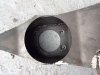
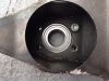
Proper bolts arrived the otherday so I took the gap bed piece out, bolted the front upright blank to the faceplate

and started boring a hole!

New front hub bearings should hopefully be here today, as the "trial" ones I had were rather used/rusty don't want to get too close to final size until I confirm the diameter and aren't going to be floating around in there!
Also ordered a whole load of CDS tube the other day along with some spherical bearing housings, bearings, a few turnbuckles (so I can accurately adjust the "suspension" rather than use a shock). I've got an order nearly ready to go to the laser cutters as well for the end plates on the front arms.
Also worked out as I have a milling/vertical slide with a "V" I can use the lathe as a tube notcher as well.")
Proper bolts arrived the otherday so I took the gap bed piece out, bolted the front upright blank to the faceplate
and started boring a hole!
New front hub bearings should hopefully be here today, as the "trial" ones I had were rather used/rusty don't want to get too close to final size until I confirm the diameter and aren't going to be floating around in there!
Also ordered a whole load of CDS tube the other day along with some spherical bearing housings, bearings, a few turnbuckles (so I can accurately adjust the "suspension" rather than use a shock). I've got an order nearly ready to go to the laser cutters as well for the end plates on the front arms.
Also worked out as I have a milling/vertical slide with a "V" I can use the lathe as a tube notcher as well.