
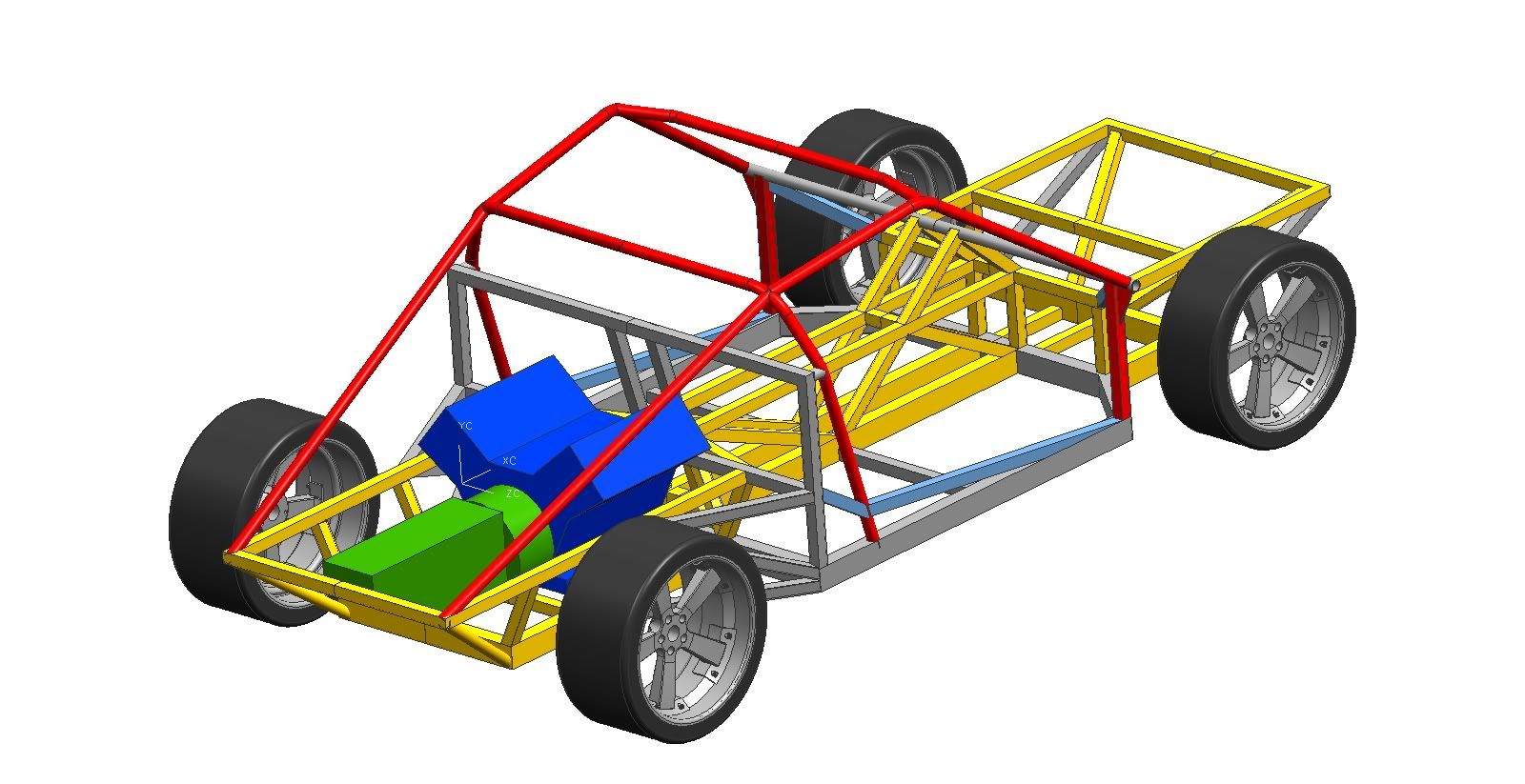
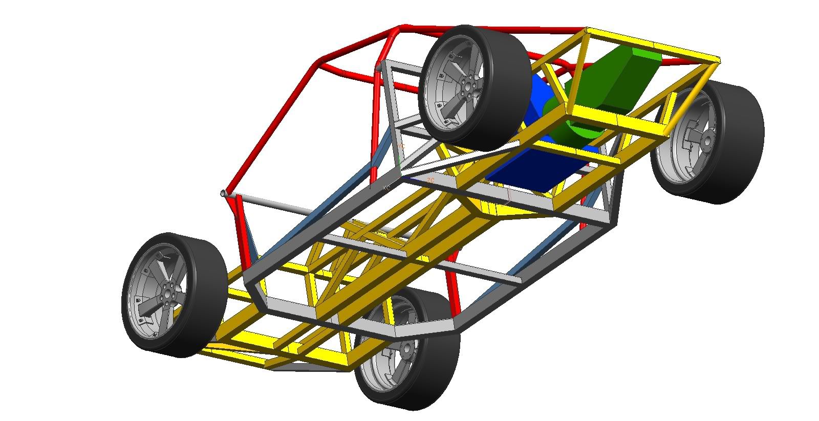
yesterday, i finally finished the cut list for my chassis and determined the total weight based off the cut lengths and a catalog. the current design uses 2"x3" 11 gauge tubing for only the bottom-most parts, including the box surrounding the passenger bay, the backbone, and the front and rear suspension/motor mounts. the a, b, and c pillars are to be made of 1.5" 12 gauge round tubing. all else (main backbone structure, upper suspension mounts, etc.) is to be made with 1.5"x1.5" 12 gauge tubing. and the total weight, not including any other component or the angles cut out of the tubes, comes out to 512 pounds. that just seems rather heavy to me. :uneasy: i'm sure a lot of weight will come off when the tubes are cut to fit together (there's a lot of bizarre angles), but there's still the aluminum shear panels and the 400 lb audi engine. with the goal weight being 2400 lbs, i'm a little concerned. dare i adjust any tubing sizes to something thinner than .10 inches?

You are using an out of date browser. It may not display this or other websites correctly.
You should upgrade or use an alternative browser.
You should upgrade or use an alternative browser.
ideal weight for steel tube space frame?
- Thread starter 700west
- Start date
Chris Duncan
Supporter
"2"x3" 11 gauge"
this is not a Cobra. With a GT40 tube frame the main beaming strength front to rear is accomplished with a triangulated section of 1.5"x1.5" tubing 10" high. Compared to a Cobra with 2"x4" tubing and that's it. In other words a 10" high cross section in the main force direction compared to a 4" high cross section.
Of course the Cobra reference is for a basic ladder frame, there is better out there.
1.5"x 1.5" should be the largest cross section anywhere with a lot of 1"x1" on diagonals etc. You might consider 12 gauge for all the main members and 13ga or ever 14ga for some of the diagonals etc.
You should look at round 1-5/8"x .125 wall on the roll cage, you'll meet more sanctioning rules that way.
You're weight should come in under 400 lbs for a sub 2400 lbs car. My chassis came in at 375.
Mind you have to be careful going to 12ga, all your welds have to be really good and no big grinding at joints or drilling big holes without doublers.
Last edited by a moderator:
Hi Eric,
My frame with most brackets on it is ~150kg (330lb).
A lot of people would describe that as fat, but it depends what your goals are.
My frame is mostly made from SHS 25mm x 1.5mm (1" x 0.60") apart from the roll frame etc.
I'm using a Toyota V8 and aim to have a complete weight of 1000kg for the car.
yea, i figured it was heavy.:worried: my original reason for the 2"x3" tubing was to either use aluminum or get down to really thin walls. reducing it down to 1.5" square would mean major modifications to the model and cut list with hours or work that i'm really not prepared to do after years of working on paper and 6 months in CAD. i would post a screenshot, but i have none on this computer and my memory card got stuck somewhere in the cheap reader in my work one, so i have no way to explain the design in more detail.
would reducing the 2"x3" to 1.5" square really make any difference anyway? i'd lose about 1.7lbs/ft in weight, which accounts for about 51 lbs, just going from memory. even in a lightweight car (a prototype, mind you), that's a lot of work for seemingly little benefit.
would reducing the 2"x3" to 1.5" square really make any difference anyway? i'd lose about 1.7lbs/ft in weight, which accounts for about 51 lbs, just going from memory. even in a lightweight car (a prototype, mind you), that's a lot of work for seemingly little benefit.
would reducing the 2"x3" to 1.5" square really make any difference anyway? i'd lose about 1.7lbs/ft in weight, which accounts for about 51 lbs, just going from memory. even in a lightweight car (a prototype, mind you), that's a lot of work for seemingly little benefit.
Carrying the extra weight is one thing, accelerating & stopping with extra weight is another, think ''light'' all the way thru your project-- it all adds up--or down in this case
")
Chris Duncan
Supporter
I checked the records, my chassis is 375 lbs with all the sheeting.
I spent 1 year cad drawing starting with measurements from an Integrity chassis and a MK-V.
"would reducing the 2"x3" to 1.5" square really make any difference anyway"
50 lbs is a lot on a race car and you'd save more than that if you also reduced all your wall thicknesses. If you have any kind of diagonals in the length direction I would at least reduce all the wall thicknesses.
It depends what you want though. It's one thing to build from scratch and it's another thing to also design from scratch. I kind of designed from scratch and don't know if I'd do it again.
You can get a good idea of what a 1.5" chassis is supposed to look like from all the pictures. The Tornado, KVA, Roaring 40's, CAV are all similar.
yes, that's true. at least with the current design, a lot of mass is down really low, but i'll look into doing a copy of the model with the 2"x3" eliminated and see what comes out of it. many tubes are vertical, so they'll be simple. the painful part is having to readjust the angles of the tubes in the backbone structure as well as the angled ones in the door sills.
getting back to kalun's advice about the 1" diagonals, i'd probably keep 1.5" in my case since the only ones in the design are in the backbone. that's where i want the most stiffness, and it's not a bad location to have a lot of mass (in the center, rather low). shear panels will be triangulating anything else that needs it.
getting back to kalun's advice about the 1" diagonals, i'd probably keep 1.5" in my case since the only ones in the design are in the backbone. that's where i want the most stiffness, and it's not a bad location to have a lot of mass (in the center, rather low). shear panels will be triangulating anything else that needs it.
Did you read this thread? http://www.gt40s.com/forum/gt40-tech-chassis-brakes-tires-wheels/22530-chassis-weight.html
If I was building a road car I would go for 35 or 38 mm with 2mm wall thickness. That is pretty overkill but lot easier to work with than 25 x 1.6 and more durable over the long term. I actually used 25x13x1.6 for the diagonals the narrow side being fixed to the alloy sheet
If you want to see how light you can go, have a look at my build thread. http://www.gt40s.com/forum/gt40-build-logs/16138-kiwi-scratchbuilt.html Chassis detail about P5 I think.
alright, so i need to lose at least 100lbs. well, what i'll do is modify the cut list (hooray excel!) for all 1.5" square apart for the roll bars (and try them at .125" wall thickness) and possibly make the diagonals in the backbone structure 1" square. that should make quite a difference, and will take me all my free time tomorrow. then i'll get to modifying the model.
since this change potentially puts more stress on the shear panels, what's an advisable thickness for the aluminum and what rivets would be a good choice?
since this change potentially puts more stress on the shear panels, what's an advisable thickness for the aluminum and what rivets would be a good choice?
one issue is i'm learning welding in the process of building this (sad, i know, but true:embarassed, so i'd need lots of practice in order to avoid blowing a hole in anywhere. second, something about a wall thickness less than .10" scares me.
i dunno... this weight issue is slowing me down right now, but at least i'm at a stage where i can make multiple models and cut lists and see which is best.:thumbsup:
, so i'd need lots of practice in order to avoid blowing a hole in anywhere. second, something about a wall thickness less than .10" scares me. i dunno... this weight issue is slowing me down right now, but at least i'm at a stage where i can make multiple models and cut lists and see which is best.:thumbsup:
I bet 15-gauge (0.067") mild steel tubing would be plenty strong for the majority of chassis members with good welds and adequate triangulation.
Chris Duncan
Supporter
i'd need lots of practice in order to avoid blowing a hole in anywhere.
.063" is not that hard to weld. One trick with MIG is to stop and start during the weld, don't move the torch out of position just let off for a second or so, let it cool and start again. You can tell by the color, when it starts to get bright white it's time to let off.
second, something about a wall thickness less than .10" scares me.
You need to get over that, airplanes have a .050" aluminum skin that is part of the structure, so did the Apollo moon missions. Strength does not necessarily come from throwing thick metal at something, but from design.
what's an advisable thickness for the aluminum and what rivets would be a good choice
approx .075" on the floor, about .050" all structural, as thin as .025" for non-structural. Minimum 6061-T6, 2024 and 7075(not formable) if you can find it cheap is better.
the best rivet ever from Hansen Rivet.
the AD6270UG, way stronger than a hardware store rivet (at least 2x). Flush break, extended grip range. It's too much trouble to keep track of thicknesses, this rivet gets them all. It's a structural rivet that's affordable, about $.25 ea compared to a aircraft Cherry at about $1.25 ea.
Structural Blind Rivets - Hansonrivet.com
Reminds me I need to do a tech article about rivets, just like steel, not only the strength but the design of the rivet pattern.
i just tweaked the cut list for thinner side walls on all the tubes but the roll bar tubes. the roll bar tubes are still at .109" and everything else is at .083", and the prospective weight is now 399lbs. much better.:thumbsup: i also made a copy of the cut list to see what the weight would be with the base tubing converted to 1.5" square, and it went down to about 347lbs with just that change. i think that extending other tubes (and lots of them) would bring a lot of that weight back.
Terry Oxandale
Skinny Man
Reminds me I need to do a tech article about rivets, just like steel, not only the strength but the design of the rivet pattern.<!-- google_ad_section_end -->
Would be very nice for the tenderfoots
Similar threads
- Replies
- 1
- Views
- 4K
- Replies
- 15
- Views
- 13K
- Replies
- 9
- Views
- 11K
- Replies
- 17
- Views
- 9K