
You are using an out of date browser. It may not display this or other websites correctly.
You should upgrade or use an alternative browser.
You should upgrade or use an alternative browser.
James' GT-Forté scratch build GT40 MkI
- Thread starter harvs
- Start date
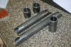
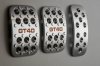
Will hopefully take delivery of these soon...
Found a guy on ebay from Serbia who makes the pedals and kindly did a GT40 version with a gulf oil coloured engraved logo.
Can you put the site up for us please ....
John.
Mike Pass
Supporter
Hi James,
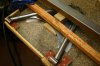
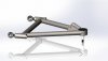
That lower wishbone is a bad design which has been known to bend and fail. There are two design issues.
The first is that the shock mounting is too close to the pivot. It should be nearer the upright to reduce the bending moment.
The second is that the loading is in the centre of a flat sheet. Flat sheet is very weak in bending. The whole weight of the car is concentrated on this point as well as shock loading from suspension movement over bumps. Flat sheet is weak, a U channel is better, a tube or box is the best for strength and rigidity. Try to make tubes connect in a triangle which is the best structural arrangement. So linking the two outer wishbone ends will be better. Also the two ends which attach to the chassis are relying on the strength of the chassis and brackets to prevent them spreading under braking loads. A tube connecting the two inner ends will prevent the ends from spreading.
It can be strengthened by moving the shock mount bracket outwards and mounting it on a tube linking the two wishbone tubes or by boxing between the two tubes towards the outer end of the two wishbone tubes. Linking the two tubes in this way will greatly improve the strength and rigidity of the wishbone.
Cheers
Mike
Hi Mike
Thanks for the comments.
I'm following the wishbone design which others building a GT-Forte chassis are using. I've read about the Tornado wishbones bending and understand the GT-Forte design to be stronger...
The tubes are 1" 12swg CDS
The plate is 5mm thick and extends further forwards
Under the 5mm plate, below the U bracket, there's a 5mm solid cross tube running between the wishbone legs
Yep, guy is called Luka and his ebay site is here
Thanks James ....
Howard Jones
Supporter
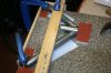
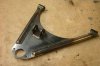
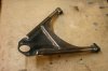
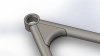
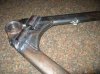
I love these scratch builds. Lots of real talent on this forum. Here's a lower A arm I do like a lot because of using the crossbar inboard in the first picture. You can see that the major load path is fed nearly directly into the lower ball joint position.
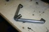
In the second picture I really like the complete gusset that surrounds the shock pick up point. Shock ears not installed yet but I would put them as far outboard as possible.
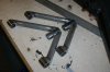
The last is of a push rod type. Here you can see where the load is being put into the arm as far outboard as possible and into the arms themselves including a nice gusset.
In the second picture I really like the complete gusset that surrounds the shock pick up point. Shock ears not installed yet but I would put them as far outboard as possible.
The last is of a push rod type. Here you can see where the load is being put into the arm as far outboard as possible and into the arms themselves including a nice gusset.
Attachments
Last edited:
Nick
Here is a previous reply from Mike to an enquiry from James.
Hi James,
Without taking the car apart here is the best I can come up with. I have measured the holes in the hub carrier which hold the carrier to the upright. They measure 10.63mm 0.419". According to my Zeus thread chart the clearance hole for 10mm bolts is 10.2mm. However the Ford bolts seem to have a thicker part of the bolt shank to centralise them.
Many of these parts for Granada Mk3/Scorpio are getting a bit rare but many are common to the Sierra. Look for breakers on Ebay or locally but they are thin on the ground now.
Here is a link to similar on Ebay
Genuine Ford Rear Hub, Bearing Bolts x 4 Sierra,Escort,Kit car, RS, Cosworth | eBay
You could ask them if they are suitable or indeed what the thread size is.
If I remember correctly they have a sort of sticky blue Ford thread lock gunk on them.
As an aside the big nuts which hold the hubs together are handed and must be replaced with new if removed as the they are a kind of nylock nut. They also need to be tightened very tight to 200 ft lbs which can only be done with the wheel on the ground. I use a big 3/4" torque wrench to do this. I will look up the nut and socket size if you need it.
Cheers
Mike
Typical response from a very generous guy and a long time supporter of this forum who has been a great help to me over the past year and to many others for a lot longer.
It's obvious you don't know Mike Pass but I believe an apology would be in order.
Bob.
Nick
Here is a previous reply from Mike to an enquiry from James.
Hi James,
Without taking the car apart here is the best I can come up with. I have measured the holes in the hub carrier which hold the carrier to the upright. They measure 10.63mm 0.419". According to my Zeus thread chart the clearance hole for 10mm bolts is 10.2mm. However the Ford bolts seem to have a thicker part of the bolt shank to centralise them.
Many of these parts for Granada Mk3/Scorpio are getting a bit rare but many are common to the Sierra. Look for breakers on Ebay or locally but they are thin on the ground now.
Here is a link to similar on Ebay
Genuine Ford Rear Hub, Bearing Bolts x 4 Sierra,Escort,Kit car, RS, Cosworth | eBay
You could ask them if they are suitable or indeed what the thread size is.
If I remember correctly they have a sort of sticky blue Ford thread lock gunk on them.
As an aside the big nuts which hold the hubs together are handed and must be replaced with new if removed as the they are a kind of nylock nut. They also need to be tightened very tight to 200 ft lbs which can only be done with the wheel on the ground. I use a big 3/4" torque wrench to do this. I will look up the nut and socket size if you need it.
Cheers
Mike
Typical response from a very generous guy and a long time supporter of this forum who has been a great help to me over the past year and to many others for a lot longer.
It's obvious you don't know Mike Pass but I believe an apology would be in order.
Bob.
Agreed Bob, not a good day all around for me yesterday. Apology in full.
Mike Pass
Supporter
That is interesting as he also says:-
"Another way to help is to move the shock absorber point further outboard to reduce the bending stress in the wishbone leg. This is a sensible move, but, will require a different spring rate and damper rate to standard to accomodate for the change in geometry. This can also cause issues with clearance on the top wishbone. Even with this solution it's nice to blend the stress in the wishbone legs out over as great a distance as possible.
These failures are not limited to the GT40 manufacturer concerned. Their wishbones are essentially the same as a Westfield 7 replica wishbone, in that the genearl size, shape, materials/thickness are the same. The polybush housings are identical etc. If you look on some of the Locost forums you'll see similar issues where people have copied the Westfield style and ended up with bent lower arms even in road use.
The results of these items bending and breaking is obviously extremely dangerous, but, as you can see from the results of the analysis very easy to rectify, and I'd highly recommend that you get them rectified sooner rather than later."
I am in agreement about the moving of the shock absorber/damper to a point further outboard as this will greatly reduce the bending moment on the wishbone. In comparing GT40 wishbones to westfield type items I would think that as the GT40 is a lot heavier and will reach far higher speeds that the wishbones on a GT40 should be significantly stronger. The change in spring rate is easily calculated from the ratio of the original distance of the bracket from the chassis end pivots to the new distance. Coil over springs are easily available in a vast range of lengths and rates.
I am also very much in agreement about the result of bending and breaking of these highly stressed components and was the motivation for my original comments. I have done well over 150mph on numerous occasions and the thought of a wishbone letting go when you hit the brakes at that speed is very scary. I have personally witnessed two lower wishbone failures which fortunately did not result in personal injury but a fair bit of car damage. One was very worrying as the car had been doing over 120mph a few minutes before and actually failed as the car was being reversed. Lucky escape. I am therefore concerned that no one else suffers these issues - or worse.
I will try to post some pics of GTD wishbones which I had on a hillclimb/sprint car and which have some features which could improve the strength and safety of your type of wishbones.
Cheers
Mike
JAMES, Stop and listen to Mike, it is imperative that you take note of the experience of others than rely on your own intuition, and we have all seen failures in this design of wishbone, your design is particularly weak, and just because it follows what another manufacturer has done do's not make it any safer.
Charlie Farley
Supporter
Frank,
100% correct, as usual, boring..lol
100% correct, as usual, boring..lol
Hi Mike
Thanks for the comments.
I'm following the wishbone design which others building a GT-Forte chassis are using. I've read about the Tornado wishbones bending and understand the GT-Forte design to be stronger...
The tubes are 1" 12swg CDS
The plate is 5mm thick and extends further forwards
Under the 5mm plate, below the U bracket, there's a 5mm solid cross tube running between the wishbone legs
We are not all following this design James.
I took note of Mike's advice and bought 4 ball joints and 4 retaining cups from Mick at Southern GT several months ago.
I am moving the spring mounting outboard on the lower and not using the drag link on the upper.
Going to use rose joints on all 4 mounts to chassis.
I would like to add that your workmanship really does look excellent.
Bob.