Jimer's Build

Build Progress-Week of 08/16/2013:
With Mike still on vacation and George still tending to his wife; I've been flying solo again this week.


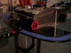
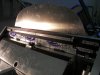
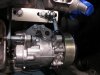
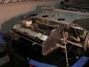
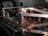
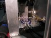
You don't really appreciate the extra sets of hands until there not there. Case in point...my back ordered fuel tank sending unit arrived so I pulled the fuel tank (again) so I could drill/tap and flush the tank (again). You may remember that a few weeks ago we made a bulk head to separate the fuel compartment from the engine compartment. Because of the protrusion of the fuel fill nipple into the engine compartment, the bulk head and fuel tank must be removed as one unit. (pic. # 002)There is a bit of a sequence combination to removing these two. I don't think that I have Alzheimer's (yet); but sometimes....I just forget to remember. This is an instance when the extra sets of hands (and brains) would have come in handy!


Horns:
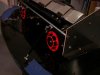
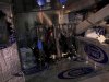
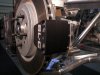
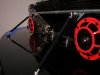
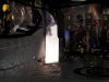
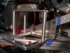
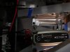
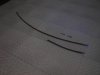
I installed a set of HLA Horns (P/N-003399801 Summit Racing-$59.97) on each side of the radiator nose piece. (pic. # 003) I would have preferred bending the mounting brackets 90* so that the horn face would be parallel with the front of the radiator. However, the directions warn against doing so; claiming that bending the bracket will effect the audio quality. Not being an audio expert...I simply followed directions. Although, I am considering fabricating two 90* “L” brackets and attaching the horn brackets to my “L” brackets. But for now the horns are just running straight of the radiator side panel. The horn bracket is a little unusual; rather than a signal piece of 1/8” stock, the 1/8” thickness is comprised of three thin pieces of stock. I assume that there is a reason for that, I just don't know what it is?


Speaking of Directions:
With all the parts I've been receiving, I've acquired quite a stack of manufactures directions. Managing them without misplacing them for possible future reference has become a problem.
Solution: I bought a cheap 3-hole punch (Staples) for the shop and I now put the manufactures installation/maintenance directions at the beginning of each related topic section in my SL-C Build Manual 3-ring binder.


Fuel Tank Sending Unit:
Here's a heads-up for those builders that want to pre-order supplies and tools pre-delivery. You will need a tube of Permatex Black Silicone Adhesive Sealer (Carquest P/N 81158-$7.68) to seal the cork gasket of the sending unit to the tank mounting plate. You will also need a 31-32 drill bit to drill a hole large enough to accommodate the collar on the sending unit pick-up tube. You cold use a 15'/16” bit and file to enlarge. A 31-32 hole is very slightly larger than you need but I didn't see a problem with that. I used Red Permatex Threadlocker on the five 10-24X1-1/4” socket head bolts I drilled/tapped to secure the sending unit head.


A note of caution that is mentioned in the SL-C Build Manual but probably worth repeating here. The mounting holes are NOT symmetric, so it is important to orientate and mark each hole individually.


Bulk Head Sound Deadening:
While I had the bulk head out, I applied a couple of coats of Sound Boom spray on sound deadening and a layer of Thermo-Tec “Cool It” heat shield.


Tube Stock End Caps:
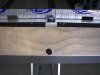
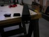
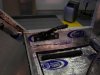
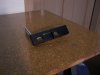
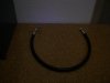
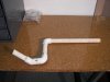
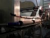
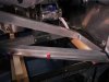
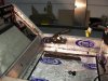
In post #33 I talked about using 1”X2” rectangular tube stock as risers for my seats. I picked up some nice end caps to finish of the open ends of the channel. (pic. # 001) Additionally, I liked Ken's suggestion (post #55) of using the rectangular tube as a chase way for the hand brake cable. I plan on drilling a hole in the center of the end cap and insert a grommet to protect the cable from chaffing.


Jim
 

Attachments

  • SL-C Build-Week Ending 08-16-2013 003.jpg
    SL-C Build-Week Ending 08-16-2013 003.jpg
    123 KB · Views: 519
  • SL-C Build-Week Ending 08-16-2013 002.jpg
    SL-C Build-Week Ending 08-16-2013 002.jpg
    139 KB · Views: 476
  • SL-C Build-Week Ending 08-16-2013 001.jpg
    SL-C Build-Week Ending 08-16-2013 001.jpg
    87.2 KB · Views: 473
Jim, the front nose inner panels when placed on the car come mm's up to those radiator/frt. bay side panels -- looks like your horns should be moved to the inside of those panels.
 
Jim, the front nose inner panels when placed on the car come mm's up to those radiator/frt. bay side panels -- looks like your horns should be moved to the inside of those panels.


Mike, I looked at that but it was hard to measure because I have the body panels stored out of the way, up in the air on my lift. I'll take another look , thanks for the in-put.
Jim
 
Jim, looks like it coming together well. It's amazing all the things one has to think about when doing a car. Thanks for thinking of me on the seats. That's one area that gets left out or "let the upholstery shop figure it out". It's looking great and I enjoy following the build.

Mark
 
Jim, looks like it coming together well. It's amazing all the things one has to think about when doing a car. Thanks for thinking of me on the seats. That's one area that gets left out or "let the upholstery shop figure it out". It's looking great and I enjoy following the build.

Mark

Thanks Mark, were getting there...to quote a good mutual friend of ours: “I just keep working the problem, problem after problem, after problem, after....”! And to quote another very good friend of mine....
“it's like eating a large bull elephant...just one small bite at a time” I counter by saying; “I equate it to:
“that large bull elephant is standing on my foot....it hurts like hell....but all I keep thinking about is how darn good it's going to feel when he gets off”!


Yes Mark, I think of you when ever I'm working on the interior. Example; I just installed the hand brake to the street side of the door ledge. Rather then just through bolting the fabricated hand brake bracket, I made some sand-off's for the bracket and turned the bolts into studs so you will be able to carpet behind the assembly and not have to cut around it. Also, when I cut out the the sound deadening material for the foot well floor pan, I made a cardboard cut-out and saved it for you to use as a carpet template. Now the front vertical wall of the drivers foot well is a whole different story. I certainly don't want to be you when you carpet that. There are check valves and brake/clutch lines; I haven't figured out any easy way to do that for you. However; knowing you...I'm confident that you probably have few tricks up your sleeve....I sure hope that you're not claustrophobic!:laugh:
Jim


P.S Folks, I know that Mark is to modest to blow his own horn, so I'll do it for him. This guy is the Micheal Angelo of interior (if Michael Angelo drove a Porsche)! I have to travel 250 mile to the “Big City” to have Mark do my interior but I wouldn't consider anyone else! Not only is he a true craftsmen, he also has a very creative imagination. Case in point: I came up with a very neat seat design that will tie-in the general theme of the the car from front to rear (more on that later). Mark loved the design and came up with two ideas to accentuate my design. The net result is that I'm going to have an extremely lush interior with an ultra modern Euro production car appeal!


Mark is of that rare breed that... even after as long as he has been doing this, he still gets excited about each project and doesn't regard it as just another job. I can't wait to get the car to him so he can start his creative magic! I feel that even I'm going to be surprised with the finished product. I have so much confidence in this guy talents that I granted him license to make any creative tweak’s he see's fit.
 
Last edited:
Thank you very much for your kind words. I get to do my hobby everyday and for that I am truly grateful. The carpet pattern will be very helpful and no I'm not claustrophobic. I do get myself into some tight spots and odd positions to get the correct fit. To quote Roger as he told me often "think of the Challenge", I go into each project with that in mind, so handling the carpet at the toe board will not be a problem. My enthusiasm for a project is enhanced that much more when a customer, like your self is very excited about the project and wants more than just a basic interior. Your interior idea is fantastic and will be my pleasure to bring your dream to reality.

Mark
 
Build Progress-Week Ending 08/23/2013:
Mike is back from vacation, :thumbsup: all relaxed and ready to go, so we stared by tidying up a few items that I wasn't very pleased with; ie. horn, throttle pedal, fuel tank sending unit and engine/fuel cell compartment bulkhead access door (more on these below). I also installed the parking hand brake handle and we addressed a potential problem with the A/C compressor mounting bracket.


Horn's:
You may recall that I was unhappy with the horns mounted on the side of the radiator housing and was contemplating fabricating an “L”-bracket so horn would face forward. Then Shark posted a caution regarding possible body clearance issues (is this forum great...or what). That was the push I needed to fabricate the 90* brackets and mount the horns in front of the radiator. (pic. #001)


Throttle Pedal:
I wasn't pleased with the short throw on the throttle linkage. Mike lengthened the rear linkage bracket thus increasing the throttle throw to slightly over 3-1/2 ”; which feels much better. An additional benefit is that the throttle pedal is not as stiff now. We also cleaned up the hose routing's and bundled them to prevent interference with the pedals.


Fuel Sending Unit:
I discovered that the fuel tank cover would not fit properly because it was hitting the newly installed fuel sending unit. There are several ways to rectify this; however, I decided that the easiest way was to make a 1/2”X1” aluminum stand-off. (pic. #002)


Engine/Fuel Tank Compartment Bulkhead Access Door:
I made an access door which would allow me access to the fuel tank shut off valve and the fuel filter on the Facet Lift Pump. Originally, I mounted a piece of angle on the top outside of the door and screwed a thumb bolt into the bottom of the 2”X6” vertical member. This kept the door closed but was very clumsy to operate, trying to blindly thread a small thumb bolt up into the chassis member.


My solution was to make small strike plate with a 1/4-20 screw threaded into the strike plate and protruding through the door and secured with a wing nut on the engine compartment side. Easy to use and a piece of anti-vibration self adhesive rubber on the strike plate eliminates any rattle! (right side of pic. #002)


Hand Brake Handle:
I made bracket for the parking brake hand brake handle from 1”X2” tube stock; finished it off with some plastic end caps and mounted it to the street side of the door ledge. I mounted the bracket on studs with stand-off's so that the upholster will be able to easily install the carpet. (pic. #004) I also installed a rubber grommet on each side of the bottom of the fuel tank compartment to route the parking brake cable to the rear wheels. (bottom of pic. #002)


Air Conditioner Compressor Bracket:
The top A/C compressor bracket is constructed from some 3/16” steel stock. There's a 3/8” tapped hole on each side of a 1/2” stand-off cast on the engine block. The cast stand-off rests in the center of the 3/16” bracket. This presents a potential problem of bending the mounting bracket when you torque down the bolts. This potential problem could be easily rectified by simply stacking a bunch of washers.
However, we felt that a car of this stature is deserving of a little classier solution. Mike tacked a 3/8” piece of stock with a notch for the engine stand-off to the the compressor bracket....problem solved!
Jim
 

Attachments

  • SL-C Build-Week Ending 08-23-2013 001.jpg
    SL-C Build-Week Ending 08-23-2013 001.jpg
    101.1 KB · Views: 418
  • SL-C Build-Week Ending 08-23-2013 002.jpg
    SL-C Build-Week Ending 08-23-2013 002.jpg
    138.8 KB · Views: 410
  • SL-C Build-Week Ending 08-23-2013 003.jpg
    SL-C Build-Week Ending 08-23-2013 003.jpg
    163.3 KB · Views: 420
  • SL-C Build-Week Ending 08-23-2013 004.jpg
    SL-C Build-Week Ending 08-23-2013 004.jpg
    156.9 KB · Views: 400
  • SL-C Build-Week Ending 08-23-2013 005.jpg
    SL-C Build-Week Ending 08-23-2013 005.jpg
    135.5 KB · Views: 407
Last edited:
Build Progress-Week Ending 08/30/2013:
I'm a little late in posting my weekly up-date due to many things going on in my life! September 1st. Will mark the two month anniversary since I took delivery of my SL-C. Look at the progress and draw your own conclusions. I don't know if I'm doing good, average or if I'm just a slacker?


For the first time in a long time the trio is all together. George's wife is feeling much better so he returned this week on a part time basis. We took advantage of the extra manpower by placing the cabin section of the body onto the chassis for a dry fit to determine the available space to run the A/C lines. The extra mussel also came in handy to dry fit the radiator nose piece in order to mock up the coolant, A/C and lift kit hydraulic lines. Additionally, we tackled the A/C compressor installation, rear parking brake calipers and 5 point race harness mounting studs.


Radiator Nose piece:
Real estate in the front radiator nose piece is getting very scarce and much heavier than when we first removed it! The only other thing left to mount in this area besides the wiring is the lift kit hydraulic lines. The A/C lines are just dry fitted in place and we'll have to remove them again to have them crimped. (pic. #001)


Of all the items we tackled on this project; the A/C system coolant/heater lines seems to be the most challenging and time consuming. Trying to figure out how to run the lines and anticipate what future item they may intrude with has been perplexing (P.I.A) to say the least.


The routing of the line has us reinventing the wheel; case in point: the supplied ed 90* elbow on the lower condenser hose running to the drier just plain didn't work. The bend was too radical and kinked the hose. I tried a 45* fitting and that exasperated the problem. I tracked down a #6 “U” fitting and that worked like a charm! (pic. # 002 & 003). My new problem is trying to feed the 90* fittings on the compressor/top condenser line through the the radiator port. I'm looking for possible alternative hose routing or mechanical, thread to thread connector solution.


A/C Compressor:
Mike made a belt tension-er for A/C compressor; now I need to determine what model belt to use.
(pic. #004)


Parking Brake Calipers:
We got the parking brake calipers drilled/tapped and installed; (pic. #005) now all I need is the new RCR cable and we can call that project complete. It sure feels good to say....something is complete (almost):thumbsup:


5 Point Racing Harness Studs:
I installed studs for lap belt and the crouch strap of the 5 point race harness. The studs will allow one person to install/remove the belts and make life a little simpler for the upholster.
Jim
 

Attachments

  • SL-C Progress-Week Ending 08-30-2013 001.jpg
    SL-C Progress-Week Ending 08-30-2013 001.jpg
    136.9 KB · Views: 412
  • SL-C Progress-Week Ending 08-30-2013 002.jpg
    SL-C Progress-Week Ending 08-30-2013 002.jpg
    108.5 KB · Views: 389
  • SL-C Progress-Week Ending 08-30-2013 003.jpg
    SL-C Progress-Week Ending 08-30-2013 003.jpg
    100.9 KB · Views: 422
  • SL-C Progress-Week Ending 08-30-2013 004.jpg
    SL-C Progress-Week Ending 08-30-2013 004.jpg
    139.7 KB · Views: 434
  • SL-C Progress-Week Ending 08-30-2013 005.jpg
    SL-C Progress-Week Ending 08-30-2013 005.jpg
    124.5 KB · Views: 447
Looking great Jim! What is your ETA on completion? It seems like you are flying along. Keep up the great work... :thumbsup:


Thanks Michael; back in January when I placed my SL-C order, I set an ETA of October for a completion date and have since amended my ETA several times. I have had so many snafus and surprises that I'm done setting ETA's (and budgets) :shrug: The way things are going;....”I'll just be happy to live long enough to see this thing finished”! How's that for a goal? :chug:


What's the latest ETA on your delivery?
Jim
 
I have had so many snafus and surprises that I'm done setting ETA's (and budgets) :shrug: The way things are going;....”I'll just be happy to live long enough to see this thing finished”! How's that for a goal? :chug:

Same as mine. Recently was able to get back at it! For a guy that could build a Cobra less than a month, this is painful. Originally guessed at a two month build (reasonable for the SL-C). Physical issues, early retirement, etc. put me WAY behind the curve.


Jack, for some reason I thought that you were up and running. I didn't realize that you are still in the build stage too (now I don't have to be jealous of you any more). :laugh:


I can certainly relate to “physical issues”....darn doctors keep cutting into my build time; I guess there not car guys! I shall just follow your words of wisdom and.....“Git-Er-Done”!
Jim
 
Wish that I was up and running. It's coming together very nicely now though.
I still refuse to set a firm ETA. Have done a bunch of tangental modifications
and fabrications, adding to the timeline expotentially (as they tend to do). Ask Mesa!
 

Michael Fling

Supporter
Not really sure of my arrival? I am getting the new interior tub that is not quiet ready, and I know that the flywheel and misc. parts for the Graziano are close. I would rather wait another week or so to have everything completed before delivery.
 
Build Progress-Week Ending 09/06/2013:
It doesn't look like much but we actually managed to get quite a bit accomplished this week. These were the small almost invisible items that needed to be addressed; and that all takes time. We drilled holes and installed the two missing motor mount bolts, cleaned up some hydraulic lift pump and A/C lines, hooked up the street side radiator coolant hose, installed some foam and rubber to prevent chafing of the coolant and hydraulic hoses, relocated the horn relay to the curb side after discovering that the horn relay wire in the ISIS loom didn't not reach to the street side, painted the steering column black and a few more little tasks such as these. Other than possibly having to relocate an electrical connection on the ceiling of the foot well, the steering column should be ready to install.


Because of the brake & clutch lines, we had to make some stand-off's for the” P-clamps” that secure the coolant lines to the 45* portion of the street side of the foot well wall. I live by the adage that:
“if can go wrong....it most likely will”! So we installed the front wheel to confirm that there is enough clearance to turn the wheel to full lock without the tire hitting the coolant line. Guess what....it didn't hit! How did that happen?


Mock-up - Curb Side Radiator Hoe:
We mocked up a radiator return hose line out of some PCV tubing and sent it to the radiator shop to be fabricated out of 1-1/2” aluminum pipe. (pic.#001)


Left Foot-Foot Rest:
I made a very simple left foot rest out of 3”x3” angle stock. (pic.#002). Not only does this provide a place to rest my left foot, it also protects the aluminum brake line that protrudes from the street side wall into the driver's foot well. While we were custom fitting the seat and pedal location for me, I discovered (in between making rrrum, rrrum, RRRUMMMM, engine sounds) that the protruding brake line was like a magnet drawing my left foot to it. It didn't take a fortune teller to predict that this was a potential problem just waiting to rear it's ugly head!


I notched out the top left side of the angle that mounts to the wall to accommodate the protruding left brake line. The foot rest is secured to the wall with a 3/8” studs and to the floor with two 3/8” studs. The suds will provide for quick/one person removal as opposed to through bolting. I'll paint the bracket black so that it will disappear into the black carpeting. The upholster will apply some adhesive backed non-skid material to the foot surface.


ISIS Wiring:
Probably the most apparent sign that we actually accomplished something, is the installation of the ISIS controller's and the wire looms. (pic. #003 & #004) We started running some of the ISIS wires and plan to start on the GM harness next week. We haven' made any final hooks-ups to any of the accessories yet but it appears that some of these leads will be too short and we'll have to extend them (i.e. the left & right rear lights are in a “Y” loom; there is no way that they will reach the booth right & left tail lights without either splitting the loom or extending one set).


Two Questions:
    1. I'm thinking of installing a piece of 1/4” plate as a floor pan on the passenger side of the engine compartment. The pan would be mounted horizontally on the frame rails, thus covering the hole between the curb side frame rail end the center engine mount rail. (see pic. #5 for location I'm referring to) The purpose of the pan is to provide a mounting location for the GM Controller Module and the GM Fuse box. I have noticed that that other builders mount these items on the vertical bulkhead. However, I was eying that space for a vertically mounted fire suppression system.
My question is: (finally), do you think that the described pan will significantly reduce air flow to the engine compartment? I should mention that I' m considering two 5.2” SPAL fans to exhaust some of the hot air regardless if I utilize the floor pan set up or not!


  1. The ISIS has a provision for the telescopic wheel; however, we're unable to locate a wire for the tilt feature. I wondering how you other SL-C builders wired the tilt.

It's starting to come together; hopefully, I'll receive my back orders next week and will be able to have a very productive week.
Jim
 

Attachments

  • SL-C Build Progress Week Ending 09-06-2013 001.jpg
    SL-C Build Progress Week Ending 09-06-2013 001.jpg
    164.5 KB · Views: 355
  • SL-C Build Progress Week Ending 09-06-2013 002.jpg
    SL-C Build Progress Week Ending 09-06-2013 002.jpg
    108.4 KB · Views: 355
  • SL-C Build Progress Week Ending 09-06-2013 003.jpg
    SL-C Build Progress Week Ending 09-06-2013 003.jpg
    139.8 KB · Views: 363
  • SL-C Build Progress Week Ending 09-06-2013 004.jpg
    SL-C Build Progress Week Ending 09-06-2013 004.jpg
    161.5 KB · Views: 389
  • SL-C Build Progress Week Ending 09-06-2013 005.jpg
    SL-C Build Progress Week Ending 09-06-2013 005.jpg
    124.8 KB · Views: 371
Jim
I strongly suggest you do NOT mount the ECU in that location...mount it vertically and out of any debris/water collection...the ECU is not waterproof to the degree needed for sitting on a horizontal panel in an area where it will get soaked

Here is a picture of the rear loom installed on Rumbles car..
http://www.gt40s.com/forum/attachment.php?attachmentid=67261&d=1378518576

Vicki will send you the invioce for the Graziano support parts next week and Dean will take care of shipping them to you asap

The ISIS system has all the connectors...there are multiple plug in connectors for all the appropriate wiring for the tilt and tele functions..
 
Last edited:
Jim
I strongly suggest you do NOT mount the ECU in that location...mount it vertically and out of any debris/water collection...the ECU is not waterproof to the degree needed for sitting on a horizontal panel in an area where it will get soaked

Here is a picture of the rear loom installed on Rumbles car..
http://www.gt40s.com/forum/attachment.php?attachmentid=67261&d=1378518576

Vicki will send you the invioce for the Graziano support parts next week and Dean will take care of shipping them to you asap

The ISIS system has all the connectors...there are multiple plug in connectors for all the appropriate wiring for the tilt and tele functions..

Thanks Fran on all 3 counts! Good advise on the ECU... I guess I'll go back to the drawing board and scout out a new location for my fire suppression system.
Jim
 
Build Progress-Week Ending 09/13/2013:
The big brown truck made a couple of stops here this week but he didn't bring Graziano parts I've been waiting for! However, my Optima Battery Mount, and back ordered Parking Brake Cable did arrive, so I installed them. I had to modify some wire routing in order to mount the steering column, but everything is neatly tucked away and out of the way. We also finished dry routing the GM harness over the engine and split the loom and ran a separate loom loon so that the electronic throttle control wires could be routed through the fuel tank tunnel to reach the accelerator pedal assembly.


This was pretty much an exercise in futility, because when we were done , we had to pack the loom into a box and back on the shelf. We have to remove the engine and transaxel to install the Graziano parts when they arrive. It's beginning to feel like I spend as much time dismantling as I do assembling. I also had to uninstall the shifter and shifter cables, box them up and send them back to RCR for an exchange for the proper shifter and cables.


Optima Battery Mount:
I fabricated an aluminum back plate with a bottom flange (pic. #001) to secure the rear of the battery mount to the diagonal frame rail and support the rear of the battery mount. I secured the front of the battery mount by through bolting it to the horizontal frame rail. The front left mounting bolt is not visible because it threads directly into round battery mount column.


On-board A/C Battery Charger:
I installed my on-board CTEK A/C battery charger to the top of the battery mount triangle hold down. (pic. #002) I used a 3/8” thumb bolt for the left rear fastener. If I have to remove the battery, I simply remove the two socket heat bolts and loosen the thumb bolt to swing the hold down along with the CTEK charger to the rear and out of the way. I plan on running the black A/C cord to the rear and splice in a weather proof marine connector mounted in the license plate area of the rear clam.


Parking Brake Cables:
It was difficult enough drilling a straight hole through the wedge shaped double wall fuel tank compartment ledge, so didn't want to press my luck by having to drill two straight holes right next to each other. Therefore, we went off the reservation and came up with a different design which would only require one hole. (pic. #003) We reversed the design, placing the cable adjustments inside the fuel tank compartment and replaced the supplied “U” clevis on the parking brake handle with an offset one and some all thread (threaded rod) on the parking brake handle linkage. (pic. #005) We put some black shrink tube on the rod:
  1. so that it would slide in and out of the hole easier when the parking brake is engaged/disengaged.
  2. To make disappear into the black carpet.

The drivers side parking bake grabs beautifully, the grab on the passenger side is not equal to the drivers side. I'll have try making some additional adjustments before I cut the cables....and I'm all out of energy for today! I don't want press my luck anymore than I all ready did on Friday the 13th.

Someone on another thread asked if the cables came precut to length. The answer is no. Picture # 006 shows the amount of surplus after cutting the cable & housing. The cable housing in the foreground is the surplus from the passenger side; its fairly obvious that the passenger side is pretty tight and the routing requires some preplanning. The other cable housing is the surplus from the drivers side (plenty to spare). The amount of surplus on the right & left caliper spring is the same.
Jim
 

Attachments

  • SL-C Build Progress-Week Ending 09-13-2013 001.jpg
    SL-C Build Progress-Week Ending 09-13-2013 001.jpg
    136.7 KB · Views: 343
  • SL-C Build Progress-Week Ending 09-13-2013 002.jpg
    SL-C Build Progress-Week Ending 09-13-2013 002.jpg
    108.4 KB · Views: 314
  • SL-C Build Progress-Week Ending 09-13-2013 004.jpg
    SL-C Build Progress-Week Ending 09-13-2013 004.jpg
    135.4 KB · Views: 329
  • SL-C Build Progress-Week Ending 09-13-2013 005.jpg
    SL-C Build Progress-Week Ending 09-13-2013 005.jpg
    187.2 KB · Views: 330
  • SL-C Build Progress-Week Ending 09-13-2013 006.jpg
    SL-C Build Progress-Week Ending 09-13-2013 006.jpg
    103.8 KB · Views: 312

Michael Fling

Supporter
I am so impressed with the quality and timeliness of your build. I'm thinking you should get 'er done so you can come to Oklahoma and lead the charge! Great job.
 
On-board A/C Battery Charger:
I installed my on-board CTEK A/C battery charger to the top of the battery mount triangle hold down. (pic. #002) I used a 3/8” thumb bolt for the left rear fastener. If I have to remove the battery, I simply remove the two socket heat bolts and loosen the thumb bolt to swing the hold down along with the CTEK charger to the rear and out of the way. I plan on running the black A/C cord to the rear and splice in a weather proof marine connector mounted in the license plate area of the rear clam.


Parking Brake Cables:
The drivers side parking bake grabs beautifully, the grab on the passenger side is not equal to the drivers side.
Jim

Good move with the on-board charger - you'll need it with the ISIS system.

My drivers side Emerg. brake also does not grip like the driver side. I've pulled both cables tight before locking down the 4 allen head screws. A quick visual inspection of the pass. side caliper pads with a feeler gauge appear to indicate that this side has a larger gap between the pads and rotor. The caliper adjusting bolt is for "centering" the pads, I've been advised. I guess I could always loosen the cable on the drivers side to compensate for the pass. side. I haven't investigated further yet... too busy driving the car - the weather has been awesome lately.
 
Back
Top