
- Forums
- GT40 Replica Manufacturers' Corner
- RCR Forum - RCR40/SLC/917/Superlite Aero
- The SLC Clubhouse
You are using an out of date browser. It may not display this or other websites correctly.
You should upgrade or use an alternative browser.
You should upgrade or use an alternative browser.
Joel K
Supporter
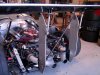
This is a minor update. For the sake of completeness I wanted to document installing the rear chassis and transaxle triangulation rods.
The triangulation rods serve two purposes. The chassis rods stiffen up the rear of the car to reduce flex. The trans rods are rear trans mounts to hold up the rear of the Graziano and also provide further chassis strength to reduce flexing.
There are multiple ways to configure the rods to increase the area to run a muffler past the k-brace. The plan is for the mufflers to fit before the end of the k-brace so I chose this configuration.
Pic of the rods and placement…

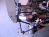
Due to shifting the engine back, the stock location for the trans rods positions them a good 2” forward of the Graziano mounting ears. I did not want to make a 2” spacer which I thought could apply too much torque and bend the mounting ears. Nor did I want to install the rods with an excessive angle reaching out rearward from the chassis to the mounting ears.
So decided to split the baby by adding washers to the ears and mount the chassis rod ends to the back of the mounting brackets instead of between the tabs…

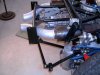
I always find excuses to use the mill so replaced each mounting ear washer stack with a 5/8” aluminum spacer and steel safety washer. Also filled in the empty mounting brackets with 1.5” aluminum spacers…

When installing the rod ends I found it best to keep the jam nuts loose and adjust the rod length as you position and tighten up the mounting bolts. Once the mounting bolts are tight, then tighten the jam nuts on the rods. This insures you don’t torque and bend the mounting ears which are a single shear design and can bend if too much torque is applied.
Here is a side pic showing the spacer on the mounting ear and the slight angle of the rod end…

Pic from the rear…

I’m in a holding pattern on installing the axles so going to mount the diffuser next.
The triangulation rods serve two purposes. The chassis rods stiffen up the rear of the car to reduce flex. The trans rods are rear trans mounts to hold up the rear of the Graziano and also provide further chassis strength to reduce flexing.
There are multiple ways to configure the rods to increase the area to run a muffler past the k-brace. The plan is for the mufflers to fit before the end of the k-brace so I chose this configuration.
Pic of the rods and placement…
Due to shifting the engine back, the stock location for the trans rods positions them a good 2” forward of the Graziano mounting ears. I did not want to make a 2” spacer which I thought could apply too much torque and bend the mounting ears. Nor did I want to install the rods with an excessive angle reaching out rearward from the chassis to the mounting ears.
So decided to split the baby by adding washers to the ears and mount the chassis rod ends to the back of the mounting brackets instead of between the tabs…
I always find excuses to use the mill so replaced each mounting ear washer stack with a 5/8” aluminum spacer and steel safety washer. Also filled in the empty mounting brackets with 1.5” aluminum spacers…
When installing the rod ends I found it best to keep the jam nuts loose and adjust the rod length as you position and tighten up the mounting bolts. Once the mounting bolts are tight, then tighten the jam nuts on the rods. This insures you don’t torque and bend the mounting ears which are a single shear design and can bend if too much torque is applied.
Here is a side pic showing the spacer on the mounting ear and the slight angle of the rod end…
Pic from the rear…
I’m in a holding pattern on installing the axles so going to mount the diffuser next.
Last edited:
Joel K
Supporter
This post covers mounting the race tail diffuser to the chassis.
The SLC has the choice of two different tail treatments, the race tail and street tail. The street tail provides enough body coverage of the rear wheels to pass certain European regulations. The race tail has an aluminum diffuser which serves as an attach point for the massive rear wing and rear clam hinge.
Here is a video on the process…
Starting with cars ordered in 2018, RCR made a slight change to the diffuser so it clears the back of the Graziano transaxle without requiring modification. The 2018 change places the center panel flat at the diffuser bottom vs. positioning it at an angle as the lower outer panels. Here is a pic of the diffuser as supplied by RCR…

The Graziano sits offset to the right and the diffuser wants to sit slightly offset to the right of the chassis as well. You need every fraction of an inch to make room for the wing upright and keep the diffuser centered. Shaving a bit off the side of the Graz rear cap helps. The offending area on the Graz can easily be filed down by hand…

As delivered, the diffuser attaches to the chassis in 4 places. Two brackets are provided for the top corners and two brackets need to be fabricated for the two lower center attach points. The builder is also expected to further secure the diffuser to either the transaxle or the K-brace. Older versions of the diffuser with smaller transaxles connected to the K-brace. Most Graziano diffuser installs attach it to the transaxle.
Since I moved the engine back 1.5” the first step was to trim out the vertical inner plates to clear the transaxle mounting ears.
The diffuser top corner brackets attach behind the top rear control arm points. As supplied, the angle and spacing of the brackets are pretty far off so decided to make new ones. Pics of the trimmed diffuser and supplied bracket…

I found a nice technique to bend up new brackets without a metal brake. Used a hacksaw to cut 1/2 way through the 1/8” flat stock. In this case a 45 degree angle works well…

Put in vice and used a hammer to fold the metal over at the cut leaving the thinner area gap on the outside corner…

Welded up the outside corner to add back thickness and strength. Custom brackets that are strong and fit perfectly. I may box the top of the bracket in to add more strength…

Pic of the new brackets held in place with cleco fasteners. Just with the clecos in place it feels very sturdy…

For the lower attach points I simply used 1/8x2x2” aluminum angles and M6 cap screws and locknuts. I took special care to locate the holes midway in the pocketed area of the lower frame cross member. Pic of the lower attach points secured to the lower chassis cross member…

Followed in Allan and Cam T’s footsteps and fabricated a couple brackets to piggy back off the transaxle mounting ears. This adds a good amount of reinforcement to firm up both lateral and vertical loads on the diffuser. Used 3/16x2.5x2.5” aluminum angle, just some scrap I had lying around and it did the job…

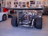
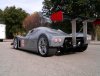
Glamour shot of the rear showing the attached diffuser and rear of the SLC…

The SLC has the choice of two different tail treatments, the race tail and street tail. The street tail provides enough body coverage of the rear wheels to pass certain European regulations. The race tail has an aluminum diffuser which serves as an attach point for the massive rear wing and rear clam hinge.
Here is a video on the process…
Starting with cars ordered in 2018, RCR made a slight change to the diffuser so it clears the back of the Graziano transaxle without requiring modification. The 2018 change places the center panel flat at the diffuser bottom vs. positioning it at an angle as the lower outer panels. Here is a pic of the diffuser as supplied by RCR…
The Graziano sits offset to the right and the diffuser wants to sit slightly offset to the right of the chassis as well. You need every fraction of an inch to make room for the wing upright and keep the diffuser centered. Shaving a bit off the side of the Graz rear cap helps. The offending area on the Graz can easily be filed down by hand…
As delivered, the diffuser attaches to the chassis in 4 places. Two brackets are provided for the top corners and two brackets need to be fabricated for the two lower center attach points. The builder is also expected to further secure the diffuser to either the transaxle or the K-brace. Older versions of the diffuser with smaller transaxles connected to the K-brace. Most Graziano diffuser installs attach it to the transaxle.
Since I moved the engine back 1.5” the first step was to trim out the vertical inner plates to clear the transaxle mounting ears.
The diffuser top corner brackets attach behind the top rear control arm points. As supplied, the angle and spacing of the brackets are pretty far off so decided to make new ones. Pics of the trimmed diffuser and supplied bracket…
I found a nice technique to bend up new brackets without a metal brake. Used a hacksaw to cut 1/2 way through the 1/8” flat stock. In this case a 45 degree angle works well…
Put in vice and used a hammer to fold the metal over at the cut leaving the thinner area gap on the outside corner…
Welded up the outside corner to add back thickness and strength. Custom brackets that are strong and fit perfectly. I may box the top of the bracket in to add more strength…
Pic of the new brackets held in place with cleco fasteners. Just with the clecos in place it feels very sturdy…
For the lower attach points I simply used 1/8x2x2” aluminum angles and M6 cap screws and locknuts. I took special care to locate the holes midway in the pocketed area of the lower frame cross member. Pic of the lower attach points secured to the lower chassis cross member…
Followed in Allan and Cam T’s footsteps and fabricated a couple brackets to piggy back off the transaxle mounting ears. This adds a good amount of reinforcement to firm up both lateral and vertical loads on the diffuser. Used 3/16x2.5x2.5” aluminum angle, just some scrap I had lying around and it did the job…
Glamour shot of the rear showing the attached diffuser and rear of the SLC…
Howard Jones
Supporter
Joel K
Supporter
Or you can do this and lose the diffuser altogether. It's really only a body/wing mount anyway
That is certainly heavy duty. Nice work Howard. I’m not planning on tracking my car, but would definitely beef up my diff mounts if I was.
Joel K
Supporter
Or you can do this and lose the diffuser altogether. It's really only a body/wing mount anyway
I like this piece, I may make two of these and have it attach to the rear clam hinge when I get to that point.
Hmmm...I think I'd replace that round diagonal brace with one made with streamline tubing. It's in the air stream so it would lower overall drag a bit.Or you can do this and lose the diffuser altogether. It's really only a body/wing mount anyway
Joel K
Supporter
This post covers trimming the bell-cranks so they clear the shock body at full droop.
The SLC build manual states the top of the shock sits in the bell-crank while the rear suspension push rod clears the upper control arm by 1mm or so when the suspension is at full droop.
I installed the shock in the bell-crank just to see how it all fits together. Pic of the shock edge contacting the bell-crank…

After looking at how the shock end hits the bell-crank I felt it could be improved to provide more travel. Ken and Johan also trimmed the bell-cranks so figure I would do the same.
Without this modification, to install the rear shock it must be compressed about an inch. Not a real problem if you are using the stock 7” springs, you can loosen the spring collars which allows you to compress the shock.
The 7” springs tend to be on the short side and considering the extra weight of the LT4 I opted for 8” 850 lb springs. This pic shows the max angle of the bell-crank and where the opposite end of the shock sits at full extension…

Ideally I’d prefer the shock end to clear the bell-crank when the shock is at full extension. I think this makes it easier to service(install/remove) the rear shocks. So fired up the mill and got to work.
Milled the area where the corner of the shock contacts the bell-crank and filed down the inside area where the side of the shock body would rest…

Here is a close up of how the shock now sits in the bell crank…

Wound up removing a little bit more material on the side so the shock bottoms out and still clears the bell-crank. The top plate requires a little more trimming than the bottom plate. Pic of the final modification…

Shock now in full droop on the chassis and clears the bell-crank…

Added the 8” Hyperco 850lb springs.

The spring rubs ever so slightly on the top of the chassis depending on how it is clocked. I’ll probably add a 1/16” spacer on the bottom of the shock end to insure there is clearance.
The SLC build manual states the top of the shock sits in the bell-crank while the rear suspension push rod clears the upper control arm by 1mm or so when the suspension is at full droop.
I installed the shock in the bell-crank just to see how it all fits together. Pic of the shock edge contacting the bell-crank…
After looking at how the shock end hits the bell-crank I felt it could be improved to provide more travel. Ken and Johan also trimmed the bell-cranks so figure I would do the same.
Without this modification, to install the rear shock it must be compressed about an inch. Not a real problem if you are using the stock 7” springs, you can loosen the spring collars which allows you to compress the shock.
The 7” springs tend to be on the short side and considering the extra weight of the LT4 I opted for 8” 850 lb springs. This pic shows the max angle of the bell-crank and where the opposite end of the shock sits at full extension…
Ideally I’d prefer the shock end to clear the bell-crank when the shock is at full extension. I think this makes it easier to service(install/remove) the rear shocks. So fired up the mill and got to work.
Milled the area where the corner of the shock contacts the bell-crank and filed down the inside area where the side of the shock body would rest…
Here is a close up of how the shock now sits in the bell crank…
Wound up removing a little bit more material on the side so the shock bottoms out and still clears the bell-crank. The top plate requires a little more trimming than the bottom plate. Pic of the final modification…
Shock now in full droop on the chassis and clears the bell-crank…
Added the 8” Hyperco 850lb springs.
The spring rubs ever so slightly on the top of the chassis depending on how it is clocked. I’ll probably add a 1/16” spacer on the bottom of the shock end to insure there is clearance.
Last edited:
Joel K
Supporter
Time for a little work in process on the exhaust system. This is the last major item to fabricate before I start the electrical.
I probably have 50+ pics of various SLC exhaust setups. I had a few requirements for the exhaust and wanted to incorporate the following features into the system:
1)ODB2 emissions compliance with front and rear O2 sensors
2)EPA-ODB2 400 cell certified catalytic converters
3)Street Resonators - keeps the drone down
4)Optional Street Mufflers - keeps the volume down
5)304 Stainless - Long lasting
Here is a short video covering part 1 of the exhaust fabrication…
A few installs in particular caught my eye and decided to leverage some other builder’s approaches:
1)Fabricated down pipes like Ken Roberts
2)Position Catalytic Converters like Johan
3)Use Vibrant Ultra Quiet Resonators like Cam T
Here is an early design sketch of what I was thinking…the Spintech mufflers in the sketch are optional. I’ll add them after go cart if the car is too loud with just the resonators…

Then took the sketch and drew out to scale cardboard patterns of the assembly from the exhaust manifold flanges to the resonators. Due to the cylinder offset of the V8 engine, the passenger down tube is longer than the driver side. I wish the actual metal fabrication was this easy…

The 2D model was placed on the passenger side. At this point it looks like it fits OK but could be tight near the rear spark plug wire, knock sensor, and rear engine mount bolts…

Here are the exhaust components and where they were sourced:
Qty 2 Vibrant 3” Ultra Quiet Resonator PN 1142 - Amazon
Qty 2 GESI 3” 400 cell High Output catalytic converters - Verocious Motorsports
Qty 4 3” tight radius 304SS 90 degree elbows - Amazon
Qty 2 Stainless LS7 flanges - Tabzone

Next step was to cut the elbows connecting the resonator with the catalytic converter and the converter to the down tube. I used a 70 degree elbow on the pattern so wanted to start with that and see how the assembly would fit in the chassis.
I don’t have a tube cutting band saw so came up with a process by using a band clamp to precisely cut and angle off the elbows. By placing the clamp at 22% of the arc length, that leaves the balance of the tube after the cut to be 70 degrees. Pic of the elbow with the band clamp in place….

Used a Dremel tool and patiently ground along the band clamp to get a very precise cut. Both the resonators and the cats have slightly oversized tubing so the elbows slip into them and allows for some adjustability of the angle and length. This makes it much easier to fit up the exhaust assembly. Pic of the two elbows attached to the Resonator and cat…

Now to see if that part of the assembly fits in the chassis or requires adjustment. For the most part looks like the cat clears the rear engine mount plus leaves enough room for heat shielding for the rear spark plug wire, knock sensor, and shifter cables.
Pic of the passenger side resonator and tube clearing the spark plug wire and knock sensor. Will probably shorten up the resonator extension by .75” to provide a bit morel space…

Pic of the passenger side cat clearing the rear engine mount…

Fitting up the driver side has it’s own challenges. The driver side flange is about 1.5” closer to the rear of the engine than the passenger side. Also, down pipe from the flange needs to clear the LT4 liquid to oil cooler. Pic showing how close the cat pipe is to the flange…

Glamour shot of the resonators in place…

Next post will cover fitting up the down tubes.
I probably have 50+ pics of various SLC exhaust setups. I had a few requirements for the exhaust and wanted to incorporate the following features into the system:
1)ODB2 emissions compliance with front and rear O2 sensors
2)EPA-ODB2 400 cell certified catalytic converters
3)Street Resonators - keeps the drone down
4)Optional Street Mufflers - keeps the volume down
5)304 Stainless - Long lasting
Here is a short video covering part 1 of the exhaust fabrication…
A few installs in particular caught my eye and decided to leverage some other builder’s approaches:
1)Fabricated down pipes like Ken Roberts
2)Position Catalytic Converters like Johan
3)Use Vibrant Ultra Quiet Resonators like Cam T
Here is an early design sketch of what I was thinking…the Spintech mufflers in the sketch are optional. I’ll add them after go cart if the car is too loud with just the resonators…
Then took the sketch and drew out to scale cardboard patterns of the assembly from the exhaust manifold flanges to the resonators. Due to the cylinder offset of the V8 engine, the passenger down tube is longer than the driver side. I wish the actual metal fabrication was this easy…
The 2D model was placed on the passenger side. At this point it looks like it fits OK but could be tight near the rear spark plug wire, knock sensor, and rear engine mount bolts…
Here are the exhaust components and where they were sourced:
Qty 2 Vibrant 3” Ultra Quiet Resonator PN 1142 - Amazon
Qty 2 GESI 3” 400 cell High Output catalytic converters - Verocious Motorsports
Qty 4 3” tight radius 304SS 90 degree elbows - Amazon
Qty 2 Stainless LS7 flanges - Tabzone
Next step was to cut the elbows connecting the resonator with the catalytic converter and the converter to the down tube. I used a 70 degree elbow on the pattern so wanted to start with that and see how the assembly would fit in the chassis.
I don’t have a tube cutting band saw so came up with a process by using a band clamp to precisely cut and angle off the elbows. By placing the clamp at 22% of the arc length, that leaves the balance of the tube after the cut to be 70 degrees. Pic of the elbow with the band clamp in place….
Used a Dremel tool and patiently ground along the band clamp to get a very precise cut. Both the resonators and the cats have slightly oversized tubing so the elbows slip into them and allows for some adjustability of the angle and length. This makes it much easier to fit up the exhaust assembly. Pic of the two elbows attached to the Resonator and cat…
Now to see if that part of the assembly fits in the chassis or requires adjustment. For the most part looks like the cat clears the rear engine mount plus leaves enough room for heat shielding for the rear spark plug wire, knock sensor, and shifter cables.
Pic of the passenger side resonator and tube clearing the spark plug wire and knock sensor. Will probably shorten up the resonator extension by .75” to provide a bit morel space…
Pic of the passenger side cat clearing the rear engine mount…
Fitting up the driver side has it’s own challenges. The driver side flange is about 1.5” closer to the rear of the engine than the passenger side. Also, down pipe from the flange needs to clear the LT4 liquid to oil cooler. Pic showing how close the cat pipe is to the flange…
Glamour shot of the resonators in place…
Next post will cover fitting up the down tubes.
Frank Clark
Supporter
The spring rubs ever so slightly on the top of the chassis depending on how it is clocked. I’ll probably add a 1/16” spacer on the bottom of the shock end to insure there is clearance.
If you switch to 2.25" springs, that problem goes away. You also get a better selection of springs.


Joel K
Supporter
If you switch to 2.25" springs, that problem goes away. You also get a better selection of springs.
View attachment 124236
View attachment 124237
Thanks Frank, that Is a very good solution. I see some machining of the collar is necessary, but that looks pretty easy to do.
Last edited:
Howard Jones
Supporter
The one thing I can advise is to take EXTREME measures to locate and shield the shifter cables. They will NOT tolerate heat in excess of about 300F at 1 inch. Distance is the solution to the problem, shielding is the bandaid fix for the problem. ALL shielding will heatsoke in still air. Airflow in the engine room is crucial. If you can run them outboard of the chassis uprights along the lower chassis elements and not anywhere near the exhaust.
The one thing I can advise is to take EXTREME measures to locate and shield the shifter cables. They will NOT tolerate heat in excess of about 300F at 1 inch. Distance is the solution to the problem, shielding is the bandaid fix for the problem. ALL shielding will heatsoke in still air. Airflow in the engine room is crucial. If you can run them outboard of the chassis uprights along the lower chassis elements and not anywhere near the exhaust.
^^^^^^^
Exactly. And if you can figure it out, solid mechanical linkage is impervious to heat. There are several examples over on the FFR818 forum of how to get mechanical linkage built.
Joel K
Supporter
^^^^^^^
Exactly. And if you can figure it out, solid mechanical linkage is impervious to heat. There are several examples over on the FFR818 forum of how to get mechanical linkage built.
Thanks Alan, I’ll check it out.
Ken Roberts
Supporter
VaporWorx just posted this tear down video of the ZL1 fuel module. A great look at it’s internal design.
Joel K
Supporter
VaporWorx just posted this tear down video of the ZL1 fuel module. A great look at it’s internal design.
Thanks for posting Ken. They certainly pack a lot of technology for a great price. Very glad I went in this direction. I had Speartech make the engine harness so it interfaces with the stock GM Fuel Pump Control Module. It should all just work seemlessly.
Also, this saved me time from having to hunt down the ohms reading on the fuel level sender(40ohms full, 200ohms dry). I needed that info. I plan to add a resistor on the second fuel sender input on the Speartech harness(dual fuel tanks on the C7 Corvette each with a fuel level sender). I think by using the actual fuel sender and showing the other at half full, it should trip the EVAP leak down test when appropriate. One of the complexities of having to pass ODB2 emissions.
Joel K
Supporter
As Sony and Cher sang “The beat goes on” in January of 1967 so the work continues on the SLC exhaust.

This post covers fabrication of the down pipes and connecting them to the cat pipes.
Here is a short video on the process…
Nothing is ever as easy as it seems when dealing with custom fabrication. Initially, the resonators, cats, and pipes seemed to fit ok, but the down pipes did not line up the way I envisioned. The LT engine exhaust flanges angle away from the engine. So if the down pipes are not angled back in, they wind up 1.25” wider than where the cats want to meet. See pic of the LT engine with Corvette exhaust manifolds angled out…

So it turned out the 2D patterns I made were pretty good but decided to mock up the down pipes in 3D before cutting anymore tubes.
First step was to attach a 90 degree tight bend elbow to the exhaust flange. As a 3D mock up, used hot glue to tack it up which works great. Grabs well and removes easily with a little rubbing alcohol…

After a few iterations came up with a design which toe the down pipes inward. This helps position the cat and pipe much better to clear the rear engine mounts. Here is a 3D mock up of the passenger side cat lining up. You can see how the down pipe toe in to meet the cat pipe flange…

Now it’s time to fabricate the down pipes.
Here are the supplies used:
Cut the 90 degree elbows with legs to a butt weld on one side. This results in the correct height. Then marked it where to cut in half...

A hand jig saw worked well to cut the elbows down each side. Also made pie cuts out of the butt weld elbow. Just like the cat pipes, used a Dremel cutting disk and a stainless band clamp as a guide to make various sizes and picked a couple that worked…

Here is a pic from above, you can see both the down pipe elbows and pie cuts have to toe in quite a bit. In hindsight less bulky rear engine mounts would have helped…

Pic of the passenger side all fitted up. Added V-band clamps at the end of the down pipes. This will make it easy to service the resonators and cats without having to remove the flange bolts. Also trimmed 1” off the resonator to make the bend and provide more clearance to the spark plug boot and wire…

Driver side down pipe ready for test fitting. Pic of the down pipe, v-band and cat tube on the driver side. It will be a tight fit, but the steeper angle of the cat and shorter pie cut makes it work…

Pic of the toe in necessary to clear the liquid to oil cooler and rear engine mounts on the driver side…

So far so good and the Beat Goes On! The next post will cover welding and installing the finished exhaust.
This post covers fabrication of the down pipes and connecting them to the cat pipes.
Here is a short video on the process…
Nothing is ever as easy as it seems when dealing with custom fabrication. Initially, the resonators, cats, and pipes seemed to fit ok, but the down pipes did not line up the way I envisioned. The LT engine exhaust flanges angle away from the engine. So if the down pipes are not angled back in, they wind up 1.25” wider than where the cats want to meet. See pic of the LT engine with Corvette exhaust manifolds angled out…
So it turned out the 2D patterns I made were pretty good but decided to mock up the down pipes in 3D before cutting anymore tubes.
First step was to attach a 90 degree tight bend elbow to the exhaust flange. As a 3D mock up, used hot glue to tack it up which works great. Grabs well and removes easily with a little rubbing alcohol…
After a few iterations came up with a design which toe the down pipes inward. This helps position the cat and pipe much better to clear the rear engine mounts. Here is a 3D mock up of the passenger side cat lining up. You can see how the down pipe toe in to meet the cat pipe flange…
Now it’s time to fabricate the down pipes.
Here are the supplies used:
- Qty 2 3” stainless 90 degree elbows. 3” radius with 6” legs - Verocious Motorsports
- Qty 1 3” stainless 90 degree tight radius butt weld elbow - Amazon
Cut the 90 degree elbows with legs to a butt weld on one side. This results in the correct height. Then marked it where to cut in half...
A hand jig saw worked well to cut the elbows down each side. Also made pie cuts out of the butt weld elbow. Just like the cat pipes, used a Dremel cutting disk and a stainless band clamp as a guide to make various sizes and picked a couple that worked…
Here is a pic from above, you can see both the down pipe elbows and pie cuts have to toe in quite a bit. In hindsight less bulky rear engine mounts would have helped…
Pic of the passenger side all fitted up. Added V-band clamps at the end of the down pipes. This will make it easy to service the resonators and cats without having to remove the flange bolts. Also trimmed 1” off the resonator to make the bend and provide more clearance to the spark plug boot and wire…
Driver side down pipe ready for test fitting. Pic of the down pipe, v-band and cat tube on the driver side. It will be a tight fit, but the steeper angle of the cat and shorter pie cut makes it work…
Pic of the toe in necessary to clear the liquid to oil cooler and rear engine mounts on the driver side…
So far so good and the Beat Goes On! The next post will cover welding and installing the finished exhaust.
Joel K
Supporter
This post covers modifying the interior tub.
The fuel tank sits behind an aluminum cover and optional fiberglass tub. The tub is really nice and creates a finished look to the interior. As delivered, once the tub is installed there is no access to the fuel tank. At a minimum, many builders create a removable panel to service the fuel sender.
Considering my build has a number of in tank components and a number of electronic and emissions components installed in that area I wanted to make it totally serviceable.
Here is a video on the process…
Here is a pic of where I think I’ll trim the panel…

First step was to make a mold of a section of the panel to verify the tank would clear. Applied packing tape on the tub and applied three layers of glass…

Applied the fiberglasss…

Mocked up panel installed and trimmed. By doing this it helped confirm the opening is large enough to remove the fuel tank only by sliding the tank over a few inches to the driver side…

Made some slight adjustments to the size of the opening based on the mocked up section and then it was time to cut the tub. Used a Dremel along the cut line, but left some small sections uncut. This keeps the panel in place while fiberglass bonding strips are applied. Similar to how Johan made his front wheel vent openings. Very clever…

Pic from behind you can see how nice the small uncut sections hold the panel in place…

Applied packing tape where I did not want the resin to adhere. Also pressed modeling clay into the slits to prevent the resin from leaking through to the other side. Applied 4 layers of 2” fiberglass tape with resin to mold in a backing strip. Fiberglass resin is cured, here is a pic behind the interior tub and you can see the backing strips…

Cut the small tabs with a Dremel so the panel was free to be separated from the fiberglass backing strips. Here is a pic of the tub after the panel was popped out without the backing strips being trimmed…

Pic of the tub installed in the chassis with backing strips trimmed. The fuel tank easily clears the tub…

Pic of the removable panel in place. It sits nice and flush. Once carpeted it will blend right in. I think this is a good compromise of having the fuel tank serviceable and maintaining the nice look of the interior tub…

Lastly, the fuel tank aluminum close out panel will need to be modified in order to clear the opening.
The fuel tank sits behind an aluminum cover and optional fiberglass tub. The tub is really nice and creates a finished look to the interior. As delivered, once the tub is installed there is no access to the fuel tank. At a minimum, many builders create a removable panel to service the fuel sender.
Considering my build has a number of in tank components and a number of electronic and emissions components installed in that area I wanted to make it totally serviceable.
Here is a video on the process…
Here is a pic of where I think I’ll trim the panel…
First step was to make a mold of a section of the panel to verify the tank would clear. Applied packing tape on the tub and applied three layers of glass…
Applied the fiberglasss…
Mocked up panel installed and trimmed. By doing this it helped confirm the opening is large enough to remove the fuel tank only by sliding the tank over a few inches to the driver side…
Made some slight adjustments to the size of the opening based on the mocked up section and then it was time to cut the tub. Used a Dremel along the cut line, but left some small sections uncut. This keeps the panel in place while fiberglass bonding strips are applied. Similar to how Johan made his front wheel vent openings. Very clever…
Pic from behind you can see how nice the small uncut sections hold the panel in place…
Applied packing tape where I did not want the resin to adhere. Also pressed modeling clay into the slits to prevent the resin from leaking through to the other side. Applied 4 layers of 2” fiberglass tape with resin to mold in a backing strip. Fiberglass resin is cured, here is a pic behind the interior tub and you can see the backing strips…
Cut the small tabs with a Dremel so the panel was free to be separated from the fiberglass backing strips. Here is a pic of the tub after the panel was popped out without the backing strips being trimmed…
Pic of the tub installed in the chassis with backing strips trimmed. The fuel tank easily clears the tub…
Pic of the removable panel in place. It sits nice and flush. Once carpeted it will blend right in. I think this is a good compromise of having the fuel tank serviceable and maintaining the nice look of the interior tub…
Lastly, the fuel tank aluminum close out panel will need to be modified in order to clear the opening.
Joel K
Supporter
This post is probably a bit premature since the initial setup and alignment of the suspension was done with some very basic tools back on post #320. Front ride height is set at 4.25”. At some point I’ll either buy a tenhulzen alignment setup or take the chassis to an alignment shop before the body is locked down for good.
Fabricated two bump steer spacers and took some measurements. I used a washer stack on the drivers side to get the tie rod angle close to the lower control arm angle. The SLC manual suggests this is the best approach to reduce bump steer.
These are the measurements I got on the driver’s side. I think these numbers are pretty good…

Then used the same sized spacer on the passenger side and it seems I may need to fabricate a slightly taller spacer to get the tie rod closer to the angle of the lower control arm..,

I could also just add a single washer on the passenger side which would probably do the trick.
Anway, wondering if most other builders have seen a difference from side to side and is the correct approach to make a taller spacer on the passenger side or is this close enough where it doesn’t really matter.
Fabricated two bump steer spacers and took some measurements. I used a washer stack on the drivers side to get the tie rod angle close to the lower control arm angle. The SLC manual suggests this is the best approach to reduce bump steer.
These are the measurements I got on the driver’s side. I think these numbers are pretty good…
Then used the same sized spacer on the passenger side and it seems I may need to fabricate a slightly taller spacer to get the tie rod closer to the angle of the lower control arm..,
I could also just add a single washer on the passenger side which would probably do the trick.
Anway, wondering if most other builders have seen a difference from side to side and is the correct approach to make a taller spacer on the passenger side or is this close enough where it doesn’t really matter.
Last edited:
Similar threads
- Replies
- 10
- Views
- 2K
- Replies
- 14
- Views
- 5K