Ken's SLC build thread

Ken Roberts

Supporter
I use the Swagelok fittings for their robust construction. I highly recommend their use. I basically don't 37 degree flare anything anymore. These are much stronger and remain "pretty" due to their stainless material. They only cost about $15 and can be purchased from most hydraulic shops. The part number is SS-600-6-6AN

For fuel lines I will only use teflon lined stainless braided or the OEM nylon tubing.. I hear of too many problems with other types of hoses with the biggest complaint being a fuel smell inbedded in the hose pemanently.
 

Attachments

  • 002-2.jpg
    002-2.jpg
    79.7 KB · Views: 508
Last edited:

Ken Roberts

Supporter
Wow! Quite impressive!

Thanks Ben and Tyson. All of these mods were accomplished with simple tools. I cut everything out of "sheet aluminum" with a reciprocating saw and shape them with a die grinder, then off to a welder if needed. The only machining was to the valley cover.
 
Holly Crap Ken you are flying, looking good. I should have had Fran poke the holes and fit the body too, would have saved a lot of time. Keep up the great work can't wait to see it done, maybe next week at this rate :)
Cheers,
Grant
 

Ken Roberts

Supporter
Next is the fitting of the attachment points for the 3 point harness that is required here (Manitoba) for street registration.

Also the custom fuel bucket that is going to be installed in the fuel tank as in this mock up picture. One inch and a half was cut from the top of the tank so that this 2002 Camaro fuel bucket will drop inside the center section. The GM fuel bucket was modified with a Walbro 255 ltr pump. Racetronix sells a kit to modify the bucket as well as selling the brand new delphi bucket assembly. I will be taking advantage of the fact the fuel bucket assembly has provisions for a fuel pressure sensor and evap hook up as my build will be incorporating all emissions features. The fuel level arm will also be used.

Modern fuel buckets act like surge tanks by the fact they have a second mini outlet at the top of the pump that supplies fuel via a mini fuel line to the bottom of the bucket where this fuel pressure spins a jet pump that sucks up fuel from the bottom of the tank that constantly keeps the fuel bucket full at all times. This should work well for a street application with occasional track days time.
 

Attachments

  • 014_zpsd0568793.jpg
    014_zpsd0568793.jpg
    68.6 KB · Views: 507
  • 002-7.jpg
    002-7.jpg
    94.3 KB · Views: 463
  • 017_zpsb66739ac.jpg
    017_zpsb66739ac.jpg
    37.9 KB · Views: 456
  • 006_zps72b82653.jpg
    006_zps72b82653.jpg
    28.1 KB · Views: 465
  • 001_zps25cc3707.jpg
    001_zps25cc3707.jpg
    39.7 KB · Views: 474
  • 003_zpsad626b05.jpg
    003_zpsad626b05.jpg
    31 KB · Views: 476
  • 005_zps2fb51e70.jpg
    005_zps2fb51e70.jpg
    33 KB · Views: 456
Last edited:

Ken Roberts

Supporter
The C5 Corvette filter/regulator saves a lot of plumbing.
 

Attachments

  • IMG_1518.JPG
    IMG_1518.JPG
    112.6 KB · Views: 464
Last edited:
I find it cheating that you've made as much progress in 3weeks as some of us have made in 3yrs :D

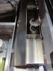
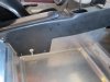
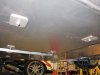
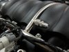
Here is a mock up picture of the K&N filter housing. The housing was shortened by about 8". The part that was removed was the curved section. This filter is actually made out of carbon fiber. I will reinstall the rear clip shortly to make sure I have clearance.

You can also see the Katech coil brackets. I modified them to be used with the stock valve covers. The coil towers were cut off and the covers smoothed.

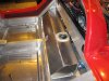
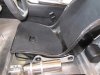
In the lower part of the picture you can see the battery tray being mocked up.

I need to raise it slightly because the handbrake lever will be installed on the left side of the driver and the cable path will aim right at the battery base.

The blue hose in the lower left of the picture is for the ZR1 oil cooler. Coolant flow leaves the heat exchanger than eventually joins up with the coolant flow leaving the water pump.

009_zps2662242f.jpg


How much room do you street tail guys have under there??? Us race tails get like 1.5 fist widths, lol
 
Wow, you are on fire!

Its been just a few weeks since you recived your SLC and it looks like you'll have a runner in no time!
 
Ken, you've obviously made good choices on how to spend your prep time. You must have also had a very good idea of exactly what you needed and how the parts would be used. This is phenominal progress. Your last name wouldn't be "Foose" would it?

I'm really looking forward to following this build, although it looks like it make be a shorth build thread.

Your work looks impeccable from what we can see so far.

Great job!
 
This picture shows the heat shield ring being fitted to the transaxle. A 6" diameter aluminum tube will be cut in half with one half for the drivers side axle shield and the other half for passenger side shield.
010_zpsaf9059a3.jpg
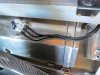
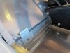
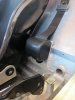
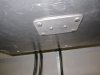
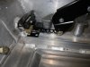
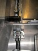
Wow, you are moving! the heat shields were a nice addition on mine. if they are long enough to extend out to the center of the CV joint, they catch the grease that could get spattered up. Will you track this car or is it for gentle street use? If its for track, have you considered putting the heavier duty ricardo axle retaining washers on? Ford GT blogs say this is a common weak link... $120 for piece of mind
 

Ken Roberts

Supporter
Thanks for the compliments. I made cardboard /paper templates for the seats and pedal assembly. When the car showed up it was very easy to center punch the exact hole locations in the aluminum floor. The bolts were spotted welded to small plates in advance that mount from the bottom. These plates are rivited in place (from the bottom) so that no one will be needed under the car to hold the bolt heads from spinning while the nuts for the seats and pedal assembly are tightened.
 

Attachments

  • 003_zps31d5072a.jpg
    003_zps31d5072a.jpg
    55.4 KB · Views: 464
  • 004_zps0183e83f.jpg
    004_zps0183e83f.jpg
    63.8 KB · Views: 446
Last edited:

Ken Roberts

Supporter
I decided to run the hand brake on the left side of the driver. I added a micro switch to the handbrake as needed for the C6 Corvette gauge cluster and for certain programming as the Tech2 programmer needs to see that the hand brake is applied before certain programming is allowed.
 

Attachments

  • 003_zps15d735c2.jpg
    003_zps15d735c2.jpg
    35.8 KB · Views: 451
  • 008_zpsb49d3212.jpg
    008_zpsb49d3212.jpg
    37.8 KB · Views: 473
Last edited:

Ken Roberts

Supporter
Here are the pictures of the seat mounting bolts/brackets.

The seat sliders sit on top of spacers/washers to keep them about 1/8" off the floor so debris won't gum up their operation. Then jet nuts hold the seat sliders in place.
 

Attachments

  • 002.jpg
    002.jpg
    43.1 KB · Views: 484
  • 001_zps25cc3707.jpg
    001_zps25cc3707.jpg
    39.7 KB · Views: 490
Last edited:

Ken Roberts

Supporter
Cam I did purchase the Accufab side bolt kit for the Ricardo. The car will be mostly used for street but up to the task for track days kinda use.
 
Ken, if you halved (cut in half) the axle cover "ring" will it still mount to the ricardo and also allow for easy removal when needed? I don't have a ricardo so don't know how many bolts are available for connection.

This picture shows the heat shield ring being fitted to the transaxle. A 6" diameter aluminum tube will be cut in half with one half for the drivers side axle shield and the other half for passenger side shield.
010_zpsaf9059a3.jpg
 

Ken Roberts

Supporter
The rings stay as shown in the picture. The 6" tube gets cut in half with one half welded to the passenger side ring and the other half welded to the drivers side ring.

The only way to remove the finished heat shields would be to disconnect the axles.

The shields are held in place by 4 bolts on each side.
 
Back
Top