Ken Roberts
Supporter

So nice and clean...
All looks great Ken... :thumbsup:
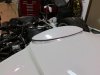
Car's looking really good. I can't wait to see how your interior turns out. I really like your third brake light and side marker lights.
I thought I had a sign that an SLC was in my near future. I was in the junkyard looking for some parts to complete a project and I spotted a Taurus wagon with a white third brake light off in the distance. I was going to get the first part for my SLC! Alas, the car was completely burned on the inside and I couldn't figure out a way to open the hatch to get it off. That's the way I roll.
Ken:
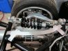
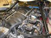
Let us know how the 750 lb springs look. Are you using 7" - 750 lb? I'm getting ready to order mine and I want to see examples before I order. Your transmission is heavier than mine? How much more weight?
I'm coil bound too.
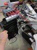
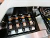
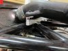
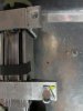
Great suggestion.Here is an important modification that all builders should consider.
My solution was to weld the bolt heads to a flat plate. This plate gets bolted in place from the bottom with 5/16" allan head bolts.. The bolts won't spin because the heads are welded to the plate.