
- Forums
- GT40 Replica Manufacturers' Corner
- RCR Forum - RCR40/SLC/917/Superlite Aero
- The SLC Clubhouse
You are using an out of date browser. It may not display this or other websites correctly.
You should upgrade or use an alternative browser.
You should upgrade or use an alternative browser.
Ken's SLC build thread
- Thread starter KENS80V
- Start date
Ken Roberts
Supporter
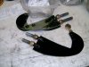
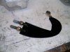
After hearing Howard describe how the tow operators yank you out of the cat nip quickly because everyone is on the clock and their lack of caring I thought it would be a good idea to over engineer that piece. The last thing I want is for it to bend and damage the body from an off angle tow/pull.
Ken Roberts
Supporter
The canards were a group purchase a couple of years ago built by a guy in the UK. They are about the widest size available while still being road legal. The track canards like on Howard's Car are cooler but would not pass an inspection for road registration. You might find a used set if you post in the parts for sale/wtb section.
I've never seen canards in front of the rear fenders.
I've never seen canards in front of the rear fenders.
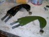
New canards
It's winter, and the driving season for this year is still months away. So this is the time to get a couple of things done on the SLC. One task was to install these carbon fiber canards on the car. Ed helped out and we got them installed in about 2 hours. It would be half that time for the...
www.gt40s.com
Last edited:
Ken Roberts
Supporter
Finally got around to building the shifter trim panel. Made it out of 22ga steel. It's glass bead blasted and ready for a silver hydrodipped carbon pattern.

Ken Roberts
Supporter
Getting ready to install the doors again from scratch with steel plates installed this time on the spyder and front of doors. I removed the 1/2" x 20 studs from the hinge and made threaded transfer punches from a couple of bolts I had laying around. I'll install the doors with wood shims for alignment then swing the hinge forward to mark the location of the holes on the steel plates on the doors. That should give me a good starting point. I have the spyder sitting on a stand so this should go smoothly for initial door alignment.


Howard Jones
Supporter
Ken Roberts
Supporter
Here's an Idea for you. Steel and 1/8 thick 4140. Stiff as hell and thin enough it won't rub.
Wow.
 Do you use struts as well Howard?
Howard Jones
Supporter
Yes, in the door so they are compressed when closed. No problem for 4 or so years. The green one was before final black paint. The other one in the same picture was what came with my early car. It rubbed on the hole in the body so I made a thin version of the exact same shape from chrome molly. The studs are welded in a slot and the female threads for the rod end is a piece of tubing suitable for 3/8-24 treads and also welded into a slot.
You can make em……….. I cut mine out with a saws all, hand fines and a sander. If you are worried make em from 3/16 and if you want to hang the car from them, 1/4 inch. Just to test, make one from 6061 T6 Aluminum and see what you think. 1/4 inch would be easy to cut out and stronger than 1/8 4140. The aluminum studs and threaded bung will not be as easy to weld as steel but a lot lighter. That's why I did mine in steel......easy to weld.
Go for it!
Last edited:
Ken Roberts
Supporter
As shown in the pictures..... the grinding is limited to the bottom side of the assembly only. I'm guessing the door flexes as it's swinging through it's ark creating excessive movement in the aluminum hinge arm. A bearing would help control the movement of the aluminum hinge better than a heim joint that pivots freely. Even a bronze bushing would be better than a helm joint but that's probably too much load on a single bushing. Both Howard's and Bob's method address the movement in the aluminum arm. Both would require a new arm to be fabricated.
These suggestions are great. Please keep them coming!


These suggestions are great. Please keep them coming!
Last edited:
Ken Roberts
Supporter
What if a roller wheel was installed where the position of my thumb is in the first 3 pictures. You can see my thumb catches the travel of the arm in all three positions. The roller wheel can have a tread out of nylon or rubber perhaps. A custom bracket to hold the wheel could be mounted/bolted to the bracket where the X is drawn in the fourth picture. The fourth picture also shows the contact path of the roller wheel.


Ken Roberts
Supporter
A track roller wheel something like this.....

 www.mcmaster.com
McMaster-Carr
McMaster-Carr is the complete source for your plant with over 595,000 products. 98% of products ordered ship from stock and deliver same or next day.
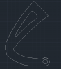
I made a CAD file that holds a bearing at the pivot. Water jet from 1/2" aluminum. Works great. No rubbing and looks good.
Bob, I like it!
Since I have the original steel version, hate the scraped up look, would prefer aluminum AND has been tested successfully - this looks like the answer for me.
May I use your file? I'd have to modify it since the steel bracket center to center of the door mount posts are narrower.
Thanks
Ken Roberts
Supporter
Bob, how did you make the hinge plate out of 1/2" aluminum when the studs that thread into it are 1/2"? Did you use smaller diameter studs?
Yes I did use 3/8" studs which worked fine. 1/2" studs were overkill !! The shape and geometry is the same as the factory unit.
Ken Roberts
Supporter
The factory aluminum hinge plates had a design change sometime around 2015. Our earlier hinge plates had the two studs center line spaced at 1 1/4". The updated design has the studs spaced at 2”. Mesa has the early design. The real early design (first few cars produced) were made from steel. Mine in 2012 were aluminum.
Last edited:
Howard Jones
Supporter
Ken. You already have the part. Mill it to a thickness that doesn't rub and be done with it.
Similar threads
- Replies
- 5
- Views
- 1K
- Replies
- 1
- Views
- 2K