Lotus 23 recreation built

Hi mates
Some year ago a few members knowing I was starting with help of my grandsons ( after the 907/8 replica built) a project of this tiny and smart 2 seater and they where
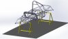
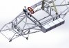
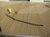
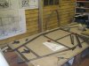
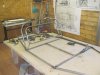
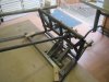
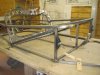
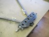
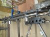
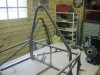
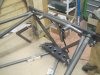
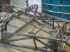
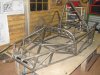
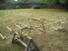
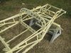
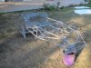
advising me to start a thread to show all the process of this built from CAD drawing to completion of the rolling chassis
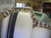
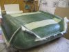
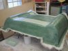
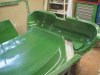
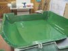
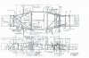
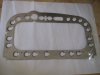
I had the big opportunity to have access to roughts 2d drawings( and also tons of dimensions of the real deal !!) and had in hand a complete bodywork to repare so access to do accurate molds
At the time I was too busy to document such a thread ; am now cool and plenty of time to do so if you good members are interested to follow such a"tale" :D
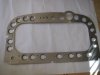
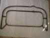
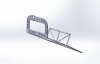
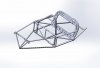
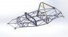
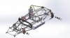
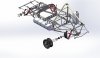
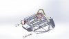
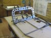
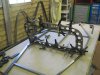
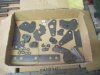
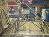
As I have done hundred pics during the built and many Jpeg views of the CAD engineering process

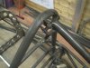
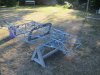
Just a"teasing pic" to show how the project started from arought internet drawing !!!

So any interest in reading such built ?????????????:rolleyes:
 

Attachments

  • c2.jpg
    c2.jpg
    73.3 KB · Views: 1,165
  • expo chassis.JPG
    expo chassis.JPG
    389.9 KB · Views: 871
Yeah go for it, lovely racecar that, and it looks like your starting with the perfect ingredients. Access to the real deal, drawings and a good body!
 
  • Like
Reactions: Mic

Ian Anderson

Lifetime Supporter
Definitely it looks like a brilliant project. I only wish I had fabrication skills to do something like that!

Ian
 
  • Like
Reactions: Mic

Neil

Supporter
Mic, this sounds like a fun project. In the "Olden Days" the roll bar wasn't so large (none). Here is a picture that I took of my fellow GI, Darryl Lander, sitting in the Lotus 23 of Hawkins/Ryan in the old Nurburgring paddock. Also one of the Ashdown/Johnstone 23. This was the 1962 ADAC 1000 kM race at the 'ring.
 

Attachments

  • Darryl Lander.jpg
    Darryl Lander.jpg
    251 KB · Views: 732
  • Lotus 23- Ashdown & Johnstone.jpg
    Lotus 23- Ashdown & Johnstone.jpg
    234 KB · Views: 735
Yes you are right !! originally they didn't have any and then a small one
And finally when the 23b started to be used on long distance races some had the roll bar I selected
So thanks for your replies mates ; will start the story few by few :rolleyes:
 
So this project started because I had the opportunity to help a good friend owner of an 23 b who was concerned about racing with the car with no spares ( suspension and body) so we decided to measure all ( I had no idea to built any at that time )
Once body was molded grandsons where saying ; hey we have done the most important why don't you draw everything and do a project with us
One of them was curious to learn about cuting and welding tubes !!!!
So when help to my friend was over ( and he was happy to be able to race with all improvment and spares we did !!) I started to draw few by few the chassis
Another good opportunity was to meetthe owner of an former UK subcontractor of original chassis ( he had a holiday house there in France not far from me !!) We where talking of this futur built and he offer to dig out some tools and do for us the biggest and more important part of the chassis ; the central bulkhead!!!!!!!!!!!!!!! ;)
So all started from this ( giving the chance to check that all dimensions on the sketches where accurate !!!!!!!!!! And PC work followed
 

Attachments

  • STA_1293.JPG
    STA_1293.JPG
    211.4 KB · Views: 643
  • STA_1296.JPG
    STA_1296.JPG
    219.9 KB · Views: 621
  • STA_1299.JPG
    STA_1299.JPG
    209.3 KB · Views: 601
  • tableau de bord.JPG
    tableau de bord.JPG
    152.7 KB · Views: 636
  • ensemble cloison moteur.JPG
    ensemble cloison moteur.JPG
    179.1 KB · Views: 634
few by few tubes are being installed on the CAD chassis ; I tried to trim them one by one in the spirit to have them done by laser !!!!
The roll over bar was also drawn in order to ask a quote to companies doing bending ( very very rare people in France !!! able to accept doing only one or 2 pieces !!!!!!!!!!!!!!!:()
 

Attachments

  • Arceau.JPG
    Arceau.JPG
    85.6 KB · Views: 590
  • ensemble cloison moteur 2.JPG
    ensemble cloison moteur 2.JPG
    152.6 KB · Views: 574
  • ensemble cloison moteur .JPG
    ensemble cloison moteur .JPG
    246.3 KB · Views: 741
While the chassis started to be all drawn I started drawing some wood tooling to tackweld the front bulkheads and trying too to draw suspensions parts definition
 

Attachments

  • montage soudure couple avant.JPG
    montage soudure couple avant.JPG
    154.6 KB · Views: 556
  • couple avant.JPG
    couple avant.JPG
    180.8 KB · Views: 530
  • ensemble cloison moteur - 2.JPG
    ensemble cloison moteur - 2.JPG
    220.7 KB · Views: 580
  • Triangle arrière équipé.JPG
    Triangle arrière équipé.JPG
    106.6 KB · Views: 543
  • demi train avant gauche assemblé.JPG
    demi train avant gauche assemblé.JPG
    205.9 KB · Views: 667
  • Chassis 1.JPG
    Chassis 1.JPG
    393.2 KB · Views: 822
Many thanks mates for your "likes" !!!:rolleyes:
So after lot of PC tribulations and hudge amount of hours ( was not used on CAD drawing, am more old fashion "pencil and white paper Man" but watching at young ingineers on the last team race (study office) I worked as Fabrication manager I understood enought by myself how to use those modern tools ......:D)
I managed to achieve all drawings necessary to start the built with grandsons
In addition doing some internet browsing I had also the big chance to meet more people involved in 23 parts refabrication with some of them( in UK ,US and Belgium) so kind to accept helping me in going forward on this recreation project.................
Those assemby drawings where printed in addition to the one found in the net in order to have a better idea of how to start in scale 1/1 the chassis
 

Attachments

  • chassis en cours de remontage.JPG
    chassis en cours de remontage.JPG
    371.2 KB · Views: 610
  • Ensemble chassis monté 3.JPG
    Ensemble chassis monté 3.JPG
    398.8 KB · Views: 1,013
  • Ensemble chassis monté 5.JPG
    Ensemble chassis monté 5.JPG
    328.3 KB · Views: 575
  • Ensemble chassis monté.JPG
    Ensemble chassis monté.JPG
    471.8 KB · Views: 652
Michel would be possible to get a basic chassis drawing off you with measurements on it, it would be interesting to compare to mine and see how close i got to being correct.
regards John
 
starting with the chassis ; I tried to be very close to the original one as it had some of round tubes carrying the engine water cooling ( in period all formula's adopted this process so Chapman used too this on the 23 ) and the square ones carrying oil !!!!
This was done just to match real deal but I was aware that to use the car on modern races will need to do external conduits !!!!
Those specific tubes where welded "apart" and tested in pressure too
Then trimming and tackwelding few by few the all thing ......................... :p :p
 

Attachments

  • 1 (2).JPG
    1 (2).JPG
    582.6 KB · Views: 565
  • 1.JPG
    1.JPG
    388.2 KB · Views: 606
  • 2.JPG
    2.JPG
    373.6 KB · Views: 563
  • 7.JPG
    7.JPG
    367.6 KB · Views: 545
  • 6.JPG
    6.JPG
    374.1 KB · Views: 615
Some more tubes going onto the chassis and all bracket being done
With good help of grandsons coming several week ends chassis is coming quite rapidly and they enjoy watching the projectcoming along so fast ;)
 

Attachments

  • IMG_1474.JPG
    IMG_1474.JPG
    317.3 KB · Views: 535
  • 21.JPG
    21.JPG
    337.9 KB · Views: 552
  • IMG_1467.JPG
    IMG_1467.JPG
    372.8 KB · Views: 556
  • IMG_1465.JPG
    IMG_1465.JPG
    308.6 KB · Views: 528
  • IMG_1480.JPG
    IMG_1480.JPG
    358.6 KB · Views: 535
Thanks again mates for all your likes !!!!! :D :rolleyes:
After 4 good months of trimming and welding the chassis started to be almost done
Thanks to a friend boss of an Kart Cross manufacturing company the roll bar was done in material similar to the ones used on the chassis (25Cd 4s) just alittle softer with possibility of doing nice bends, so was more than happy with that result
 

Attachments

  • IMG_1471.JPG
    IMG_1471.JPG
    345.8 KB · Views: 533
  • IMG_1495.JPG
    IMG_1495.JPG
    379.2 KB · Views: 537
  • IMG_1490.JPG
    IMG_1490.JPG
    342.1 KB · Views: 508
  • IMG_1515.JPG
    IMG_1515.JPG
    347.2 KB · Views: 561
  • IMG_1534.JPG
    IMG_1534.JPG
    397.8 KB · Views: 542
After checking all suspensions fit and details brackets where ok ( at that point was about a year work) I teached one of my grandson how to use compressor stuff so we started (atfer a good sanding to all tubes and tricky areas) with a cromate coat , then an 3+1 polyurethane primer and 2 days after the final coat of what we found the closiest grey from original chassis using a 2 base polyurétane paint
( I had luckily an old original rear member painted in hand so I had this part "scanned" at the paint shop so they where able to do the exact RAL mix for us !!!!!!!!;))
That week was a very sunny august week so when coats where done the chassis was layed outside to cure better than in the shed shadow!!!!!!!!!!!!!!!!!!!!!!!!:cool:
 

Attachments

  • IMG_1535.JPG
    IMG_1535.JPG
    349.8 KB · Views: 518
  • IMG_2155.JPG
    IMG_2155.JPG
    629.2 KB · Views: 523
  • IMG_2159.JPG
    IMG_2159.JPG
    664.9 KB · Views: 640
  • IMG_2164.JPG
    IMG_2164.JPG
    664.5 KB · Views: 554
  • IMG_2167.JPG
    IMG_2167.JPG
    605.2 KB · Views: 570
Yes Udo I was lucky to have arolling chassis at home for some monthes so able with kidshlep to pick up tons of pics and all needed measures
then the reverse engineering was done when that car was still home so able to correct few by few the CAD study !!!!!!!!!!!!!!!!! What helped also are the drawings I found on the net and enlarging at a very clever printing shop those to 1/2 scale was also a good help .
So when doing all tubes it was so easy !!!! and as stated what is very handly is that you can have on the same time you tackweld tbes you have laser cut parts on hand to place every single tube on good location ;)
Eventually when you are done with your actual project and want to start anew one I friendly offer you to help you in drawing watever chassis you want to built :):):)
 
Once the chassis was in agood status we wanted also to check if the body we had to mold was ok to fit so with all grandsons ( 5 of them !! ;) ) helping with wax and flanges location we started to all molds..................
 

Attachments

  • IMG_1275.JPG
    IMG_1275.JPG
    182.8 KB · Views: 528
  • IMG_1278.JPG
    IMG_1278.JPG
    374.6 KB · Views: 525
  • IMG_1285.JPG
    IMG_1285.JPG
    285.6 KB · Views: 516
  • IMG_1350.JPG
    IMG_1350.JPG
    376.8 KB · Views: 527
  • IMG_1349.JPG
    IMG_1349.JPG
    231.9 KB · Views: 510
  • IMG_1352.JPG
    IMG_1352.JPG
    317.2 KB · Views: 513
  • IMG_1353.JPG
    IMG_1353.JPG
    292.9 KB · Views: 554
Back
Top