agreed Terry, but I am not an engineer. What do you mean by the Geometry? (I know what geometry is), But what areas need to be square? It seems to me that if I lower the pivot points of the lower arm it will just raise the tail slightly when on the ground. I assumed I would then be able to adjust ride height with my suspension.

You are using an out of date browser. It may not display this or other websites correctly.
You should upgrade or use an alternative browser.
You should upgrade or use an alternative browser.
Manta Montage T First Build
- Thread starter Eric Hardy
- Start date
Hi Eric,
There is some info on this thread that may help you.
http://www.gt40s.com/forum/gt40-build-logs/38389-old-tornado-bringing-back-life-3.html#post406114
Mick
There is some info on this thread that may help you.
http://www.gt40s.com/forum/gt40-build-logs/38389-old-tornado-bringing-back-life-3.html#post406114
Mick
Eric,
Most of the Moroso units can be mounted either way. Just have to order that way. Mine is remote and in the front clip area. The beauty of it is you can mount them just about anywhere. Here ais my mounting of the alternator, a/c units.
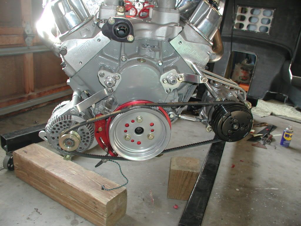
The a.c unit was just some tubng we bent and threw together.
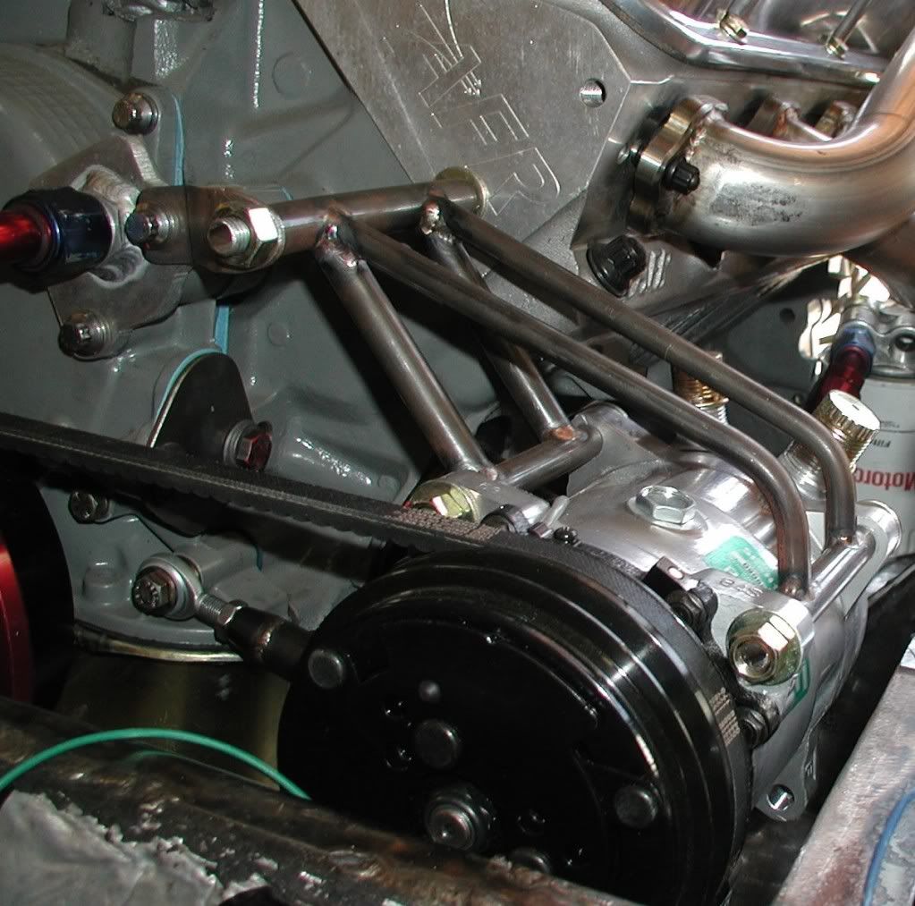
As you can see this allowed us to move the engine quite close to the firewall.
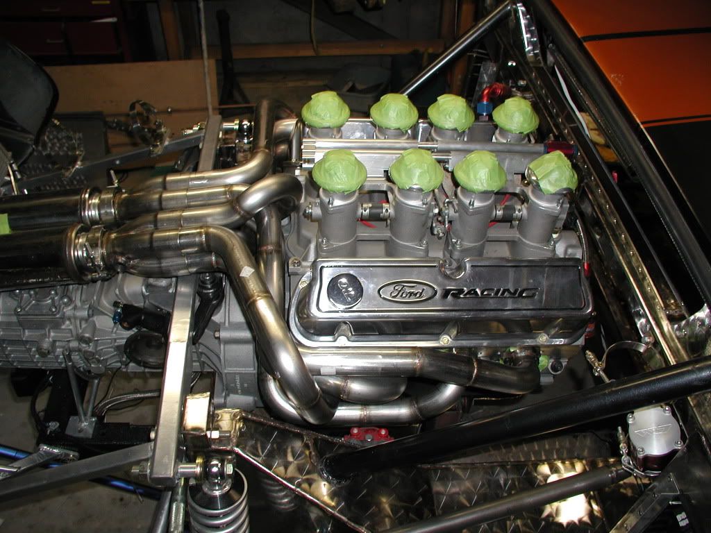
Other things you might notice is that the trans(and engine) are hard mounted to the frame. With an internally balanced engine there is no vibration to speak of.
Bill
Most of the Moroso units can be mounted either way. Just have to order that way. Mine is remote and in the front clip area. The beauty of it is you can mount them just about anywhere. Here ais my mounting of the alternator, a/c units.
The a.c unit was just some tubng we bent and threw together.
As you can see this allowed us to move the engine quite close to the firewall.
Other things you might notice is that the trans(and engine) are hard mounted to the frame. With an internally balanced engine there is no vibration to speak of.
Bill
Terry Oxandale
Skinny Man
agreed Terry, but I am not an engineer. What do you mean by the Geometry? (I know what geometry is), But what areas need to be square? It seems to me that if I lower the pivot points of the lower arm it will just raise the tail slightly when on the ground. I assumed I would then be able to adjust ride height with my suspension.
If you lower only the lower arm, you may get a geometry that will decrease camber as the chassis rolls rather than the preferred increase in camber, which will have a detrimental impact on handling. So considerations need to be made for this. Drawing out the suspension geometry on a piece of graph paper to scale will help you visualize what is happening as the suspension moves up and down with that kind of change. You could lower both the upper and lower, but that also needs to be looked at in relationship to the height of the outer pivot point locations on the uprights. When I designed my suspension, the uprights were designed around the height of the arm's mounting points, thus my axle is located high on the upright. Other's designs may have the axle low on the upright, so it's a matter of matching the mounting for both the upright and the chassis.
I would say your engine will not need to be moved any higher, and that the real problem is that the transaxle needs to be inverted (as you've suggested) to obtain the desired shaft angles.
Hi Eric,
A starting point for your suspension would be to have
The Lower wishbones parallell to the ground
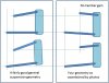
The upper wishbones approximatly 2/3 the length of the lower ones, and pointing down towards the chassis at a angle of approximatly 15 degrees, The rear wishbones need to be a more of an angle than the front ones, So the roll centre at the back of the car, is higher than the front roll centre
Here is a drawing to help you visulise it....Its not my drawing...I found it on this site

The small cross below the chassis, shows where the roll centre is.
Like Terry..... When I designed my suspension, the uprights were designed around the height of the arm's mounting points on the chassis
Mick
A starting point for your suspension would be to have
The Lower wishbones parallell to the ground
The upper wishbones approximatly 2/3 the length of the lower ones, and pointing down towards the chassis at a angle of approximatly 15 degrees, The rear wishbones need to be a more of an angle than the front ones, So the roll centre at the back of the car, is higher than the front roll centre
Here is a drawing to help you visulise it....Its not my drawing...I found it on this site
The small cross below the chassis, shows where the roll centre is.
Like Terry..... When I designed my suspension, the uprights were designed around the height of the arm's mounting points on the chassis
Mick
Last edited:
Looking through my collection of pics...Ive just realised That drawing, was probably done by the same person who owns this engine gearbox....


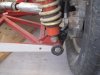
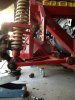
Mick, Just finished Dylan's thread. Once again I feel Im lacking in both skills and knowledge to undertake this project. However, thus far it has been cheaper than a college education so I suppose I will proceed ") Here are some pics of the existing suspension angles post driveline removal during disassembly. The angles do not look at all similar to the design you posted. It seems to me now that it would be better if I lowered the chassis mounts on the wishbones in order to obtain a more level lower a-arm Another thought I had was to weld a bracket directly to the side of the chassis. This would get the existing bracket out of the way while limiting the relocation to a minimum. This method (I think?) would also allow me to adjust the location of the connection to avoid changing the resting camber.
Here are some pics of the existing suspension angles post driveline removal during disassembly. The angles do not look at all similar to the design you posted. It seems to me now that it would be better if I lowered the chassis mounts on the wishbones in order to obtain a more level lower a-arm Another thought I had was to weld a bracket directly to the side of the chassis. This would get the existing bracket out of the way while limiting the relocation to a minimum. This method (I think?) would also allow me to adjust the location of the connection to avoid changing the resting camber.
Here are some pics of the existing suspension angles post driveline removal during disassembly. The angles do not look at all similar to the design you posted. It seems to me now that it would be better if I lowered the chassis mounts on the wishbones in order to obtain a more level lower a-arm Another thought I had was to weld a bracket directly to the side of the chassis. This would get the existing bracket out of the way while limiting the relocation to a minimum. This method (I think?) would also allow me to adjust the location of the connection to avoid changing the resting camber.Attachments
Terry Oxandale
Skinny Man
Mick's diagram is a good reference. Attached is my interpretation of how your's differs from a more ideal geometry that Mick posted. Your upper outer point is further outboard than the lower outer point, plus (and the assumption is that the suspension has insufficient weight on it to force it into the static ride height in your photos) the upper outer pivot point is lower than the upper inner (due to the angled piece at the end of the upper arm plus ball joint. In my diagrams, the upper configuration is a static ride height, and the lower pair is at bump.
If my representation of your suspension is correct (and fully loaded), then it would indeed benefit you to move both upper and lower inner pivot points lower than they are now. If you only want to change one arm, I'd say lowering the upper arm is the best bet in that case. But again, this is solely based on what I can tell from the photos.
If my representation of your suspension is correct (and fully loaded), then it would indeed benefit you to move both upper and lower inner pivot points lower than they are now. If you only want to change one arm, I'd say lowering the upper arm is the best bet in that case. But again, this is solely based on what I can tell from the photos.
Attachments
Last edited:
Terry, thank you kindly for the explanation. Looking into it more I am beginning to think that mounting it on the side would in fact reduce oveall camber a slight amount, but it would allow me to lower the driveline and center of gravity. Unfortunately my wishbones are not adjustable so it will need to be done carefully in order to obtain a neutral or retain the current resting camber.
Terry I believe you are correct on my current suspension design. Due to the increased weight of my driveline coupled with the current inadequate suspension design I think I am going to re install it this weekend with my new coilovers and set it down to gauge appropriate design changes. I am not in a rush to complete this project and therefore making it right now will be a benefit in the long run Im sure.
Terry Oxandale
Skinny Man
I am not in a rush to complete this project and therefore making it right now will be a benefit in the long run Im sure.
Great approach. You'll be much happier in the end.
Bill, I believe overall that it would be better to have a remote wp but it seems like all the remote units had a far lower flow rate than standard pully units and being in las Vegas I am always concerned about overheating. BTW if anyone of you guys are in the area feel free to pm me and come check out the project.
Thanks terry if I get to where you are on your project I will be in fantastic shape. Us manta owners seem to be few and far between and its great to have your help.
Hi Eric,
I was half way through posting a reply, then my pc crashed, but Terry has covered what I was going to say. A good book to read to help you understand suspension, is...
How To Make You Car Handle by Fred Puhn
Here are 2 pages I scanned


As you say. the best thing to do is take your time, and dont rush it..........
I was half way through posting a reply, then my pc crashed, but Terry has covered what I was going to say. A good book to read to help you understand suspension, is...
How To Make You Car Handle by Fred Puhn
Here are 2 pages I scanned
As you say. the best thing to do is take your time, and dont rush it..........
Terry Oxandale
Skinny Man
Bill, I believe overall that it would be better to have a remote wp but it seems like all the remote units had a far lower flow rate than standard pully units and being in las Vegas I am always concerned about overheating. BTW if anyone of you guys are in the area feel free to pm me and come check out the project.
I've got the Meziere 55gph pump remotely mounted that shows very impressive flow rates for 1.5" tubing, and a long circuit.
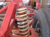
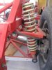
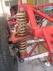
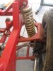
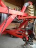
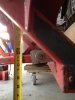
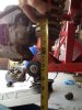
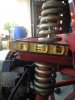
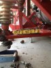
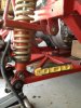
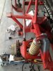
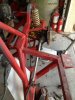
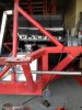
So I reinstalled the L rear wishbone suspension and semi-mounted the trailing arm and it appears the geometry is a lot better than originally thought. Take a look and let me know what you think. I put the R rear on a stand and raised the L rear with my jack until the chassis was level so there is roughly the full load on the coilover. At the moment I do believe that lowering the lower wishbone will reduce camber a bit but I dont think 2 inches will affect much. The only choices I have of leveling the lower a-arm would be to adjust the coilover or lower the lower a-arm.
Attachments
-
 IMG_0638.jpg85.7 KB · Views: 457
 -
 IMG_0639.jpg92.7 KB · Views: 546
 -
 IMG_0634.jpg69.7 KB · Views: 426
 -
 IMG_0635.jpg82.8 KB · Views: 448
 -
 IMG_0640.jpg82.2 KB · Views: 408
 -
 IMG_0641.jpg87 KB · Views: 436
 -
 IMG_0642.jpg83.9 KB · Views: 423
 -
 IMG_0651.jpg107.3 KB · Views: 406
 -
 IMG_0648.jpg97.2 KB · Views: 411
 -
 IMG_0650.jpg86.9 KB · Views: 431
Mick, Just ordered the book, looking forward to the read, thanks
Last edited:
Terry, I looked into the 55 gpm remote and I think I will go that route If I dont have enough room to run their remote mechanical pump. I like the idea of an increase of GPM at higher revs.
Meziere Enterprises
I have found quite a few 35 gpm meziere on craigslist for 200 but I am going to seer away from such a low flow.
Meziere Enterprises
I have found quite a few 35 gpm meziere on craigslist for 200 but I am going to seer away from such a low flow.
Last edited:
Terry Oxandale
Skinny Man
Eric, I would agree your situation (in regards to the suspension geometry) is much better than originally assessed. I would review the "level" reference method with the upper arm because the pivot point of the ball joint looks to be different than the centerline extension of the upper arm's inner metal (which may be good in this case due to the very short upper arm).
Have you considered moving the arms out to the side of the frame rails rather than below? Considering their current location, this may offer minimal if any change in regards to lower arms effective length.
Lastly, what are you deciding to do with the transaxle? Flipping if should lower the centerline of the shafts by about 5-6". Also, are you going to do away with the trailing link? That issue is a tough one depending on how well attached the arms are. I know on my Manta, I would be very skeptical of 14 gauge square tubing not tearing out unless the weld area was built up or the forces distributed out over a larger area than simple the welds themselves.
Terry, Moving the arms to the side of the frame rails is precisely what I had in mind, however I am going to remove the lower frame rails and replace them with 1x2 or 1 1/4 x 2 thicker stock. This will make me feel more confident in the attachments.
As for the trailing arm the upper is only connected to the car via the lower arm and upper ball joint. If the current configuration is not a hindrance to the suspension or handling I would rather leave it as is.
Regarding the transaxle I really would like to keep it in the current orientation and lower the driveline. My main reasoning for this is because the motor does not fit under the rear deck unless I swap out the current air cleaner for a low profile one. I would prefer the benefit of a lower center of gravity and more clearance as well. If I were to flip the transaxle I would not be able to lower the motor at all. It is obviously more work this way but I think I would prefer it in the long run.