WOW! With Allen and Dean leading the way, Ed, Mike, John and I have a great group. Again, I am sure I am the least experienced of the group, so if anyone sees a problem or has a suggestion, please let me know. If you see anything along the way that I can share with you, please let me know.

- Forums
- GT40 Replica Manufacturers' Corner
- RCR Forum - RCR40/SLC/917/Superlite Aero
- The SLC Clubhouse
You are using an out of date browser. It may not display this or other websites correctly.
You should upgrade or use an alternative browser.
You should upgrade or use an alternative browser.
Mark's GT-R Build
- Thread starter mksetter
- Start date
I am finally able to get started with the build. After taking inventory and putting the parts in storage, I wanted to build something, so I assembled with Tilton Pedals. As many have already said, they are nice! It is hard to know how to adjust them until they are in place, but at least I know how they can be adjusted.
Most of this build will be pretty standard, but I do have a few things that may be unusual. I want to get those started, so I don't use up space with standard things that may be needed by the few special items.
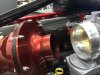
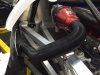
The air intake is one of the special items. I want cold air intakes using the side body scoops. I understand the Robertson race car has this feature.
The first order of business to achieve with was to decide on air cleaners. With help from contributors earlier in this build thread, I decided on K and N's cold air intake. I am aware that at high rpm levels, the air flow may be less than ideal, but is will be close.
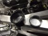
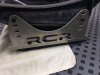
The first problem is that the 4 inch throttle body diameter down to the 2.75 inch air cleaner diameter requires an adapter that no one makes, not K&N, or anyone that I could find (see photo). Fortunately, the local Ace Hardware plumbing dept. had 4 inch to 3.25 inch adapter. I then found a an automotive piece that had an outside diameter of 3.25 and would go down to 2.75. First (of many in the future) problem solved.
Most of this build will be pretty standard, but I do have a few things that may be unusual. I want to get those started, so I don't use up space with standard things that may be needed by the few special items.
The air intake is one of the special items. I want cold air intakes using the side body scoops. I understand the Robertson race car has this feature.
The first order of business to achieve with was to decide on air cleaners. With help from contributors earlier in this build thread, I decided on K and N's cold air intake. I am aware that at high rpm levels, the air flow may be less than ideal, but is will be close.
The first problem is that the 4 inch throttle body diameter down to the 2.75 inch air cleaner diameter requires an adapter that no one makes, not K&N, or anyone that I could find (see photo). Fortunately, the local Ace Hardware plumbing dept. had 4 inch to 3.25 inch adapter. I then found a an automotive piece that had an outside diameter of 3.25 and would go down to 2.75. First (of many in the future) problem solved.
Attachments
-
 Throttle Body with Air Cleaner Showing Diameter Difference 2.JPG109 KB · Views: 786
 -
 Throttle Body with 4 inch to 3 inch adapter.JPG108.7 KB · Views: 800
 -
 3 Inch adapter showing internal hard plastic ring in place.JPG97.4 KB · Views: 658
 -
 Intake Adapter 3 inch to 2.75 inch taken apart.JPG95.5 KB · Views: 703
 -
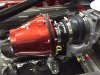 Throttle Body and adapters with air cleaner in place.JPG120.8 KB · Views: 984
If you are dead set on using that air cleaner assembly, I would atleast go on ebay and find a stainless reducer. You really need to get the fernco plumbing drain reducer out of there. They are not rated for much heat at all and very flexible.
Has the engine been tuned maf or map?
Has the engine been tuned maf or map?
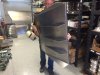
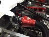
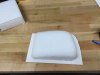
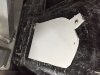
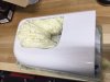
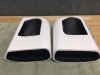
The next little project is to make a connection from the air cleaner to the side scoop. K&N includes adapters and some tubing to facilitate the connection (see photo). The supplied parts will get me down to the region of the side body scoops. I just need to make a custom fiberglass collectors to attach to the inside of the body to connect the side scoop to the K&N Tubing.
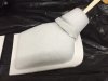
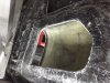
I started out with Styrofoam and developed the general shape of the mold. Styrofoam is easy to work with in some respects, but has some severe limitations. It does not glue well to itself and any solvent based materials melt it away. I am using it just as a "skeleton," then use plaster to develop the final shape. I will completely cover the Styrofoam in plaster to keep the fiberglass resin from melting the foam. At this point, I have the plaster roughed in, then after it sets, will finish the surface, paint it, add mold release, then make the fiberglass pieces, one for each side.
I started out with Styrofoam and developed the general shape of the mold. Styrofoam is easy to work with in some respects, but has some severe limitations. It does not glue well to itself and any solvent based materials melt it away. I am using it just as a "skeleton," then use plaster to develop the final shape. I will completely cover the Styrofoam in plaster to keep the fiberglass resin from melting the foam. At this point, I have the plaster roughed in, then after it sets, will finish the surface, paint it, add mold release, then make the fiberglass pieces, one for each side.
Attachments
Thanks, Scott, for your suggestion. I will get on EBay and see what other options there are. I have some heat shielding planned that should keep the upper engine bay area relatively cool and the "B" pillar air ducts will help with that also, but stainless would certainly be ideal.
Conical filters at the end of the throttle bodies certainly are an option, but I like the idea of drawing air from the outside. The race car has it. It will be great looking also.
As for the engine tuning, Katech built the motor and I will need to look at their paperwork. What is the difference between the two. You may recall that I am a novice at this.
Thanks Scott, for pointing out the need for changing the 4 inch adapter. I was able to find an automotive version from Spectre Performance. A replacement is no the way.
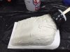
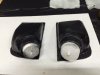
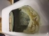
I finished the air collector molds, sanding the plaster, painting the mold, then using mold release.
Now for the fiberglass.
I finished the air collector molds, sanding the plaster, painting the mold, then using mold release.
Now for the fiberglass.
Attachments
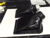
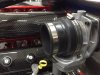
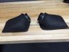
I laid up the fiberglass, removed the collectors from the molds, then trimmed to the finish lines.
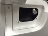
The collectors were then put in position, and two holes drilled to establish a repeatable position for cutting the hone in the body panel and the air scoop.
After the hole pattern was made, it was put on the body panel, marked, then cut. The air scoop was then cut to match.
The air flow looks good.
Now I want to work on the inside of the scoop to reduce turbulence. Foam and some gel coat should be able to "waterslide" the air flow. Photos on that later.
Attachments

These show the holes to match the air collector, then the collector in place.
Attachments
Nice work.
Has the engine been tuned maf or map?
With dual intake/TB I thought these were generally MAP. Otherwise you need a way to combine MAF output (or double one...not best idea) like with something like this
Selin Design - 2nd Gen Dual Mass Air Translator (Z32)
I'm still learning some of this stuff, but perhaps when everything is running, your achieved VE will tell you if you those filters are choking the engine.
Cars looking great!!
FYI
https://en.wikipedia.org/wiki/Volumetric_efficiency
To clarify, I don't remember which ECU you were running but you should easily be able to see what VE you are running vs target. Then disconnect that intake and see what you get. If closer to target perhaps it was tuned with the expectation of greater airflow. Just a thought.
Thanks for the feedback. I plan to run the setup by Katech to get their input. I am running Holley Dual Throttle Body Engine management, per Katech's recommendation.
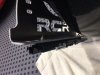
I have been disassembling the car, which is boring to the readers, but for a beginner like me it has been fun. I have been trying to mix assembly with disassembly, so I put together the Tilton pedal assembly. Wow! They are nice. I also worked on the seat position and angle, and mounted the brackets. On the driver side I am using Sparco Sliders to make that seat somewhat adjustable. The steering wheel is quite close, no matter what seat position, so I will likely add the pedal adjuster as well. The Sparco brackets are designed for brackets that mount closer together (16.5 inches), but it is no problem cutting the handle that connected the two sliders and putting a 3/8 aluminum rod to join the halves (photo later).
Attachments
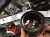
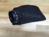
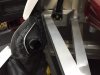
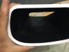
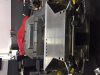
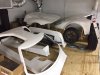
The enemy to air flow is turbulence, and the side scoop internal design causes significant turbulence. With that in mind, I added foam to the inner aspect, allowed it to cure, then trimmed it to the approximate shape that would resemble a water slide. After trimming, I painted on a coat of fiberglass resin to stiffen the foam. After a skin of body filler was applied and allowed to cure, I sanded as best I could and added a coat of flat black.
I had a chance to watch "Ford Gt: An American Icon" that was previously on the Velocity Network, now is in Amazon Videos. It is a great six episode program on the 2005-06 Ford GT. In one of the episodes, they interviewed the Robertson Racing Team, and in that interview they discussed the advantage the side scoops feeding into the air intake brought them. Hope it works. Even if it doesn't, it was fun to do.
I had a chance to watch "Ford Gt: An American Icon" that was previously on the Velocity Network, now is in Amazon Videos. It is a great six episode program on the 2005-06 Ford GT. In one of the episodes, they interviewed the Robertson Racing Team, and in that interview they discussed the advantage the side scoops feeding into the air intake brought them. Hope it works. Even if it doesn't, it was fun to do.
Attachments
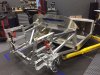
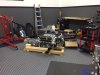
The car is now down to bare bones. I will next address the suspension. Thinking of anodizing the control arms and the spindles to make maintenance easier. Any thoughts? I have a rather large work area, and the parts are mounting up.
Attachments
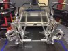
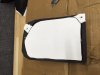
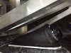
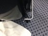
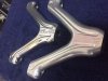
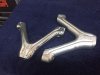
I am almost finished taking the car apart. I looked into having the suspension control arms anodized, along with the spindles. It looks like that is a good idea. I found a shop that will block out the threaded areas so they will not be affected by the process. I am now in the process of polishing all of the suspension components. The results are amazing. The photos do not do it justice. The left has been polished, the right is original finish.
I plan to use clear anodizing, which results in the thinnest added layer, so with the threads being blocked out, the parts should go back in without issue.
I plan to use clear anodizing, which results in the thinnest added layer, so with the threads being blocked out, the parts should go back in without issue.
Attachments
Similar threads
- Replies
- 3
- Views
- 2K
- Replies
- 9
- Views
- 775
- Replies
- 5
- Views
- 904
- Replies
- 63
- Views
- 6K