
You are using an out of date browser. It may not display this or other websites correctly.
You should upgrade or use an alternative browser.
You should upgrade or use an alternative browser.
Mclaren M8b replica (visual)
- Thread starter russell keach
- Start date
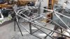
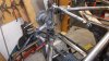
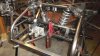
Hi all, now back on deck after 4 weeks touring and 4 weeks grounded from a small bit of personal maintenance. So now some progress, the wheels arrived and although they are 5 spoke, they are of a similar style to McLaren, I had to go 5 spoke because my rear drives(Subaru) are 5 stud and the fronts (Maxda Mx5) are 4 stud. I have fabricated up the front suspension and will now sort out where the steering rack will fit then mount the front shocks inboard via push rods. The good thing about no plans is that it can only be right after some considerable thought. I collected the aluminium adaptor plate from the laser cutters and thankfully it fits in my friends lathe to enable taking out a 10mm by 10mm recess to hide the standard Rover ring gear on the custom flywheel to the Audi 015 trans. I am working from the front of the car back, trying to think / remember all the `good` ideas from the last car. In between times, I have fabricated various bits, the rear uprights and hub assemblies are now waiting to be assembled. I have turned up new bearing carriers to fit the Subaru tapered bearings and got the flange that carries the suspension and brake caliper laser cut, so pretty soon they will be a finished component. Summit Racing has been busy sending all sorts of stuff down including the fuel tank, I have gone for an 8 gal tank this time as the car will only be a track car. On the last motor, I ran a small mechanical water pump from a Nissan and often had control / heating issues, you just never knew what the flow was so this time I will run a Craig Davies pump and bank the extra horsepower and sit relaxed cooling the motor down back in the pits with the electric option. This build is a challenge in trying to keep the costs down because my play money is well spoken for.
Attachments
Hey Russell, that looks amazing, when your done you could come build my chassis if you get bored. The race is on who will finish first, I suspect it will be you just like last time lol.
Regards
Graeme
Regards
Graeme
Hi Russell, great to see the progress and love the oval tube bottom arms, very cool. What size are the wheels, the fronts look to be about 8" wide and are you using 15s this time or something bigger, can you show us the wheels please. Will be following this build as I did the last one, you always do such nice work. Cheers Leon
Terry Oxandale
Skinny Man
Russell's knocking this one out quick!
Leon,
15 x 7 fronts and 15 x 8 rears, mainly for budget reasons as the wider I went, the greater the cost all up with tyres. I got these wheels from Palmside in Christchurch at a total cost of $1500.oo delivered to me in Auckland. As a comparison, the same wheels that I used on the first car (Performance) were quoted at $2000.00. I paid less that $1000.00 for the same wheels in 2005?. I basically have all the front suspension fabricated and set up ready to mount the shocks, after sitting the rack in place there is ample room for the. Next thing is to thread the pedals and master cylinders thru that maze. I have not mounted the rack yet as when I set it up for minimum bump steer, the tie rod ends do not appear to have enough radius for suspension travel. I am having trouble locating Mazda MX5 tie rod ends to check their fit, the ball must be angled at the outer end. I f this proves a problem then I will revert to standard rod ends on tapered bolts. I am doing the same process with the steering rack as on the previous car. Set up the drivers side rack end to the `zero` bump steer position and then extend the rack to the same position on the off side by cutting a new rack shaft the correct length...easy!
I finally sat in the frame and found that the shortened cockpit created a small challenge in mounting the removable steering boss, so had to modify the top rail of the centre bulkhead. What looked daunting to bend and refit worked out perfect first pop...thank goodness.
Sadly I have to go back to work (part time to buy car parts) on Monday so progress will slow to normal.
Cheers
I'm looking at a Mustang II rack to use possably a power unit. The Lotus uses a Spit. but with the large tires (larger contact/friction area) I'm thinking a power unit might be the way to go (but I may have clearance problems with the pump). Did you have any problems with just a standared non-power unit?
Russell
Have you thought about using an electric power steering unit? I added one adapted from a Vauxhall/Opel Corsa to my Mk1 Escort RS1600 rally car - very neat and with a rheostat the assistance can be varied or turned off.
The build up looks great!
Bill P
Last edited:
How much travel are you giving. I have settled on 3", 2" compression and 1" droop The car will ride at 3'' clearance, Even 2" compression could be to much with tyre squash as well so I may have to raise the ride height. You must have a reasonable angle on your tie rods at ride height to be binding on compression if I'm reading this right. As Terry said you are knocking this out pretty quick, a quick build is a good build!! I'm too fussy and its too complicated and Never enough Money so mine will be a long time yet. Love your work, keep it coming Cheers Leon.
Leon
Problem solved on the tie rod end, I had inserted the Escort ones (straight) in whilst checking things out. Went to BNT ON Saturday and can now see that the Mazda ones all have an angle built into them which solves that issue. Mazda MX5 ones seem hard to find so will try some other places. I am running similar heights in my set up so was surprised at that problem...all solved now. The problem when I was working was not enough time and a renewable source of funds, now its plenty of time and hard fought funds. Still this can make you think twice.
Cheers
John, can you send me your email address thanks
SUMPS
Whilst JacMac and others on the subject of sumps, I plan on cutting 25 mm out of the depth of my sump to match the gearbox to input centreline. The sump I am using is the standard Rover deep rear pan and as per my last build I was going to extend the front section, add trap doors to control oil surge and put in a horizontal plate about 60mm up from the floor. This is designed to also help oil stay own in the sump and would have some small holes and the minimum sized access hole for the oil pump pick up. Any comments.
Russell
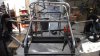
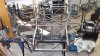
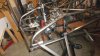
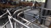
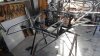
Hi, just a few photos for update as I have managed 10 hours this week. I have fleshed out the side pannier's for mounting the fuel tank and fitted both sides. The rack mounts have been tacked in place to allow space to mount the inboard front shocks so I will now have to get serious about how that will all work. Been told we are having the weekend off in the new motorhome so plenty of time to think. As an aside, I have include a picture showing how I have used the Mazda MX5 upright and standard bottom ball joint, this could have been changed to a conventional rod end if I had made up a tapered bolt to fit the upright.
Russell
Russell
Attachments
Hi
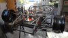
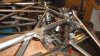
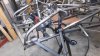
More progress, I have been setting up all the elements of the front end to endure that it all fits and works. The brake cylinders are activated by push rods from the pedals and clear the rack mounts, the inboard shocks foul a straight line push for the clutch which will be solved by a curved rod...simple. There is even room to mount the remote fluid reservoirs across the top cross member between the shocks. I have made up temporary bell cranks to check on travel and movement. There are more brackets and braces to go in now that it all appears to work. Once the car is sitting on its feet, I can fine tune the push rod lengths and maybe the ratios if needed. The steering rack has been widened and its path appears to be clear to its first universal which will be right by the top of my right foot....could be a little tight. To help with all this, I have kept everything towards the centre of the car. I will now finish of all this work and once the rain stops, head down to a local parts shop and source some Toyota Starlet / Corolla steering shafts and knuckles to complete the steering. Because I have made the front of this chassis slightly different to my first one, some things are a challenge, and I have opted to put the gear change on the RH side. Picked up the radiator today so that can be set out now that the front end is `sorted`. Had some good shed time lately so things are moving along.
Cheers :thumbsup:
Russell
Attachments
Hi there
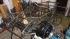
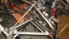
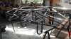
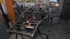
A bit more progress, got to the stage where `most` of the construction forward of the rear bulkhead has been done, fitted and removed. I have made the basics for mounting the radiator and it seems like way to far forward, yet it is correct with 100mm to spare. Not having the body available means that I have to plan on how it will fit once the chassis is painted. I have accumulated some very good drawings and information for when I build the mould so have talked myself into the fact that it will be easy! Every few weeks I get a parcel from Summit with new toys to find a home for. I have also started on getting the flywheel drawings done now that I have the clutch and pressure plate in hand. This adaption to the Audi gearbox looks to be quick and simple as I already have had the adaptor plate water cut and will run the standard Rover ring gear in a recess in the adaptor plate, this allows a standard Rover starter motor to be retained. I also have to start thinking about induction, what will I run, 4 twin chokes? a 350cfm Holley or the Rover fuel injection?
Has anyone had any experience with the Rover injection system etc, that could help me?
Next current job is to get all the construction done so that I can get a coat of paint on to stop the rust etc. This 3 day weekend was a good one with 21 hours well spent.
Attachments
Andrew Robertson
Supporter
Hi Russell, looking really good!
If you are considering a carb option, I set-up my friend's P76 Leyland powered Series 1 RX7 club race car. Used the Edelbrock 2198 dual plane with spacer plates (which you obviously wouldn't need on a 3.5) and one of the newer highly adjustable down-leg booster 750cfm (that's not a typo) double pumpers from proform/quickfuel that I had lying around. That thing lights the tyres from idle and is super responsive down low. The 4 barrel set-up was better everywhere than the 4 x 40mm twin choke Dellorto home-made cross-ram that was on the engine previously.
I used a wide-band o2 to tune it and had to put a fairly big secondary pump shot setting into it to stop a lean bog on the transition to secondaries but otherwise getting it right was pretty straightforward once I had accurate measurement of AFR available.
The main thing it re-inforced is that if you have a good sensitive and adjustable carb and a dual plane intake and heads that promote good velocity, you can go miles above the "rule of thumb" carb sizing and enjoy the benefit at mid range and top end without sacrifice. I reckon you could well make one of the new adjustable 600DP carbs work very well with some tuning, especially if you have decent heads - have a look at summit part numbers PRO-67211 and EDL-2198.
EFI would be cool too.
Keep up the good work!
Cheers, Andrew
Hi Russell,
I have a friend who has just gone through a lengthy install of a Rover efi on his offroad Range Rover. It has the 4.4 P76 engine as well. He used a Mega Squirt computer and has it running like a clock. The MS computers are good value $$$ wise and work very well although he did have a few problems untill he found a guy in Palmy Nth who is a wizard with them. If you would like me to get some detailed info off him let me know. Cheers Leon.
I have a friend who has just gone through a lengthy install of a Rover efi on his offroad Range Rover. It has the 4.4 P76 engine as well. He used a Mega Squirt computer and has it running like a clock. The MS computers are good value $$$ wise and work very well although he did have a few problems untill he found a guy in Palmy Nth who is a wizard with them. If you would like me to get some detailed info off him let me know. Cheers Leon.
Andrew / Leon, thanks for that info.
I think I will be going down the 2 or 4 barrel Holley type set up as it will be a simple user friendly set up. I am interested to learn more about setting up that larger carb so will talk later, in the meantime I will put the feelers out for a dual plane inlet manifold and see what pops up.
At the moment I am setting up the adaptor plate and drawing up the flywheel so that Jeff at Precision Engineering can knock it out.
I will have a look at the Summit site and find out more.
Cheers
Russell
Similar threads
- Replies
- 2
- Views
- 427
- Replies
- 8
- Views
- 668
- Replies
- 16
- Views
- 2K
- Replies
- 0
- Views
- 689