Hi,
I would like to build a MK IV by myself.
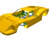
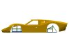
My plan is to buy the body parts from Gregg.
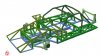
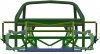
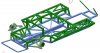
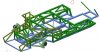
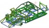
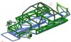
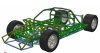
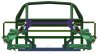
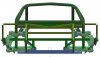
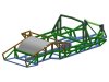
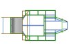
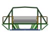
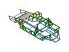
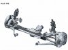
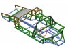
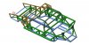
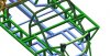
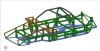
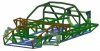
I have now constructed a frame,i found some drawings in the forum.
I changed these so that the frame fits into a MK IV.
Since I don't have any body parts yet, everything is still very unprecise.
But as a concept it should be enough at the moment.
I am not a frame designer so I would be very happy for any constructive feedback.
(Sorry for my bad english)
I would like to build a MK IV by myself.
My plan is to buy the body parts from Gregg.
I have now constructed a frame,i found some drawings in the forum.
I changed these so that the frame fits into a MK IV.
Since I don't have any body parts yet, everything is still very unprecise.
But as a concept it should be enough at the moment.
I am not a frame designer so I would be very happy for any constructive feedback.
(Sorry for my bad english)
Attachments
-
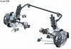
 Rahmen_GT40_MK_IV_01.JPG177.6 KB · Views: 1,060
 -
 Rahmen_GT40_MK_IV_02.JPG76.9 KB · Views: 897
 -
 Rahmen_GT40_MK_IV_03.JPG87.8 KB · Views: 829
 -
 Rahmen_GT40_MK_IV_04.JPG161.8 KB · Views: 1,022
 -
 Rahmen_GT40_MK_IV_05.JPG165.4 KB · Views: 828
 -
 Rahmen_GT40_MK_IV_06.JPG114.8 KB · Views: 780
 -
 Rahmen_GT40_MK_IV_07.JPG61 KB · Views: 878

")

")