
You are using an out of date browser. It may not display this or other websites correctly.
You should upgrade or use an alternative browser.
You should upgrade or use an alternative browser.
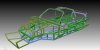
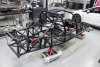
MK IV tubular spaceframe drawing
- Thread starter RexDanni
- Start date
The perimeter triangulation does nothing for torsional stiffness. Looks heavy. I would design a center tunnel running the length between the seats, the larger the better, and use sheer panels where needed instead of all the triangulation. At the rear I suspect the engine/tranny is going to be a stressed member? The rearward weight transfer on acceleration goes into the rear suspension, with the top of the shocks at that height, the only weight that transfers down onto the suspension is the weight above the top of the shock mount, not much. All weight below that point is transferred to the rear and 'locks' the suspension, does nothing for weight transfer. Course I'm not an engineer and this is worth about as much as you paid") . Good luck.
. Good luck.
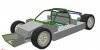
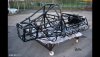
. Good luck.I've taken some of your suggestions on board now.
I also had a good conversation with a car designer.
It was hard to make the foot space as big as necessary despite the long R8 wishbones.
we have also tried to consider the crash zone issue.
Everything not so simple....
Now I'll see what the designer means.
In the appendix you can find a 3D PDF, you can hide the sheets at the layers.
The whole thing is not light but hopefully stiff and safe
The process continues ....
Attachments
I take issue with this. If the side structure/perimeter is properly built/configured, including stiff bulkheads, it will more efficiently carry torsional load than a center tunnel since they are further from the neutral axis. They also have the virtue of providing side crash protection. I might also look at a diagonal between the two rear stays. Your comment on shear panels is right, but in order to really provide shear strength, they have to be rigidly fastened to the structure. Just using pop rivets won't provide enough integrity. In this case, triangulation is a belt and suspenders approach to it, at the cost of some weight. Since this car leaves so much on the table from lack of aero/downforce etc, a little extra weight is a drop in the bucket.The perimeter triangulation does nothing for torsional stiffness. Looks heavy. I would design a center tunnel running the length between the seats, the larger the better, and use sheer panels where needed instead of all the triangulation. At the rear I suspect the engine/tranny is going to be a stressed member? The rearward weight transfer on acceleration goes into the rear suspension, with the top of the shocks at that height, the only weight that transfers down onto the suspension is the weight above the top of the shock mount, not much. All weight below that point is transferred to the rear and 'locks' the suspension, does nothing for weight transfer. Course I'm not an engineer and this is worth about as much as you paid
The biggest weakness (torsionally) that I see is through the area near the front of the side "pods". The structure needs something to tie the two pods together like a large transverse box well connected to the side structures.
Mike Pass
Supporter
Your space frame is lacking in triangulation which is important in preventing "lozenging" and contributes a lot to stiffness. I have attached a pic of a Van Diemen Formula Ford chassis to illustrate.
A central spine chassis is fine for front to rear axle stiffness. Pics of Lotus Elan and Europa chassis to illustrate. However the critical draw back to these chassis is the total lack of side impact protection.
These 3 examples are well known for excellent handling due to good torsional stiffness with lightness.
Cheers
Mike
Attachments
HJ, assuming your program does not do stress/strain analysis, it might be a good idea to build a model out of balsa wood. That will help you find where the problems are. As Bob noted, stiffness of the bulk heads is crucial, as that's where the loads get fed through the chassis, front to back and vice versa. Super stiff side pods won't keep the chassis stiff if the bulkheads lozenge. The rear bulk head is pretty easy to build stiff since it doesn't have an aperture, but the front is more difficult.
Hi,
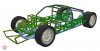
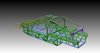
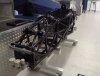
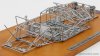
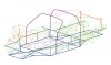
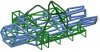
I've redrawn everything now, starting from a skeleton model.
All lines are connected at nodes.
I want to use this model in a static analysis program.
Almost everything is made of triangles
As a test and for illustration I also created the profiles.
Looks pretty heavy. There are about 500 parts
"If a Little is good, More is better, and Too Much is just enough..."
Better so...?
Attachments
Last edited:
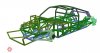
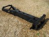
Neil - You have right-round tubes are lighter and it looks better, but for me too complicated.
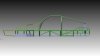
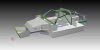
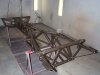
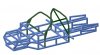
I've redesigned everything, especially the suspension area, to simplify it.
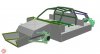
The roll cage is now fully integrated into the main frame.
I also tried to install enough bulkheads.
Especially at the front and the side I did a little bit more for crash safety.
What do you think - better?
I've redesigned everything, especially the suspension area, to simplify it.
The roll cage is now fully integrated into the main frame.
I also tried to install enough bulkheads.
Especially at the front and the side I did a little bit more for crash safety.
What do you think - better?
Attachments
Similar threads
- Replies
- 2
- Views
- 1K
- Replies
- 0
- Views
- 838