I'm looking for the diameter of the holes indicated and measurement from dash bottom to floor.


You are using an out of date browser. It may not display this or other websites correctly.
You should upgrade or use an alternative browser.
You should upgrade or use an alternative browser.
Monocoque Measurements
- Thread starter David Deschamps
- Start date
Hope this helps. I'll look for the holes in the top photo.
RegardsView attachment 127349
The print shown is the plate behind the steeringrack (2113)
The plates in question is the side of the footwell area and dash front.
Might have something on the dashboard plate but not the sideplate.
I struggled trying to work those sizes and positions as well. I think I went with some of the other nominal sizes, i.e. I would have made it 3", 3.25", 3.5, 4" or some standard size like that. think I sized them off photos or something. I have a document somewhere that has a bunch of notes in it. I was keeping a list of all the flanged hole sizes so i knew which size press tooling I needed to procure. My thinking is that it would have been a standard size based on existing tooling that they had used elsewhere in the chassis.
Ryan
Ryan
Interesting image.....
MK II stiffeners for the rear radius rods.
MK II rear firewall cutouts to allow for extra FE clearance.
Crossover fuel system
Roll cage on A pillar.
Roll cage inside B pillar on the left hand side
MK II shifter mount on side sill.
are the gold welds a silicone bronze braze?
looks like a few blind rivets in spots
also looks like a few riv-nuts in spots.
twin surge tanks on both sides of the side sills.
can also see the battery hold down bar in the passenger side foot well that was on the MK IIs, as this is where the battery was located.
fresh air duct elbow can be seen in the door pillar.
hand brake lever mount on lower dash face.
@David Deschamps for the height of the holes on the dash face, i just made them central to the dash panel. i.e. equally spaced between the top and bottom skins.
The lower edge height was adjusted based on projecting the line backwards from the spare tire mount. That panels plane bisects the vertical face of the dash. I did all this a couple of years ago when i was reverse engineering the chassis and did get some measurements from a number of separate people and the distances seemed to match up to within 1/4".
Ryan
The photo has been posted on here before. Thanks for replying all.
I'm looking for the diameter of the holes indicated and measurement from dash bottom to floor.View attachment 127348View attachment 127347
diameter of holes in dash face, I estimate they are 4.5” diameter.
I have the bottom edge of the dash flange 9.28” above horizontal zero, so there will be a closing panel below this that’s probably 0.036”.
the holes in the side of the foot box I estimated at 3.5”. The centres of which I estimate are 3.5” from the top edge of the panel. I have them 4.5” apart.
sorry for the delay in getting the measurements. I have not been able to get to my cad workstation for a couple of days. Hope that helps. I know I struggled with this for a while.
Regards Ryan
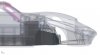
Lets see if this image loads. The view is normal to the side of foot box where the 3.5" holes are located.
Foot Box is what I have been calling this part of the car, not sure what its supposed to be called as I don't have the original drawing to reference the drawing title.

<a data-flickr-embed="true" href=" " title="Footbox_230125"><img src="https://live.staticflickr.com/65535/52645730472_9fac962bd9_h.jpg" width="1600" height="1252" alt="Footbox_230125"></a><script async src="//embedr.flickr.com/assets/client-code.js" charset="utf-8"></script>
Foot Box is what I have been calling this part of the car, not sure what its supposed to be called as I don't have the original drawing to reference the drawing title.
<a data-flickr-embed="true" href=" " title="Footbox_230125"><img src="https://live.staticflickr.com/65535/52645730472_9fac962bd9_h.jpg" width="1600" height="1252" alt="Footbox_230125"></a><script async src="//embedr.flickr.com/assets/client-code.js" charset="utf-8"></script>
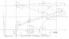
I've been working on the front subframe and I have it figured out to my satisfaction except for the measurement indicated in the photo. Front subframe tubes behind screen area distance between top and bottom tubes.Please PM me .

Sent you a PM David.
Doc Watson
Lifetime Supporter
...and one from me
")
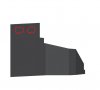
I'm now working on the motor mounts, I need the vertical location of the mount where it mates up with the block. Indicated in red , please PM me .

Approx 211mm measured from bottom of the floorpan. The engine is not level, it has a slight backwards slope, ref the angular dimensions on the print.I'm now working on the motor mounts, I need the vertical location of the mount where it mates up with the block. Indicated in red , please PM me .View attachment 129793
Thanks Ole , I'll see how that looks on my drawing.
Similar threads
- Replies
- 22
- Views
- 3K