
You are using an out of date browser. It may not display this or other websites correctly.
You should upgrade or use an alternative browser.
You should upgrade or use an alternative browser.
Norfolk Tornado
- Thread starter saxoncross
- Start date
With the water-pump now remote mounted, I’ve yet to decide how to feed the water back into the block. I can either gut an existing pump I’ve picked along the way or fabricate a water manifold to feed back into the cylinder block. I’m still debating this one.
Before I can do much more work on the engine bay coolant pipes, I need to know where the belts runs etc are. As I don’t have any bearing shells to install the crank, I’ll have to get this rebuild next before this area progresses.
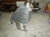
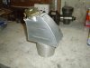
I’ve also finished fabricating the coolant header tank. This is based loosely on the MkII design and I chose this solution as it slots neatly between the body and my roll bar down-stay. It still need a couple of extra fitting (radiator & engine purge lines), but these can be added later, once I’ve worked out where they need to be on the tank.
Regards
Andy
Before I can do much more work on the engine bay coolant pipes, I need to know where the belts runs etc are. As I don’t have any bearing shells to install the crank, I’ll have to get this rebuild next before this area progresses.
I’ve also finished fabricating the coolant header tank. This is based loosely on the MkII design and I chose this solution as it slots neatly between the body and my roll bar down-stay. It still need a couple of extra fitting (radiator & engine purge lines), but these can be added later, once I’ve worked out where they need to be on the tank.
Regards
Andy
Attachments
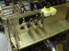
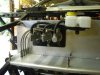
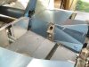
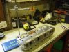
With my cylinder block & crank now away for re-machining, I finished off the main pipes for the master cylinders over the weekend. The low pressure adapters were made from some scrap stainless hex bar I had from a previous project. The reservoir and bulkhead adapters are both mounted on steel plates underneath the aluminum paneling. This not only means a tidier area, I can do all the pre-forming of the pipes before the panels are finally riveted on.
I’m still not sure if I’ll have to change the Aeroquip brake lines (clutch line will be OK) to get through the IVA test. The general consensus is that re-usable fitting cannot be used on hydraulic brake lines and all end fittings must be crimped. However the wording in the manual states that they can be used on “hose designed for high pressure applications that incorporate an inner sleeve into the compression fitting” which they have. A trip to the test station with a few sample parts is required to clear this up, other wise I’ll have to change all flexi’s to the calipers I’ve already collected.
Regards
Andy
Attachments
Hi Andy, I´ve just finished reading all of your posts about building your GT40 and I've gotten really really jealous of it. Great job, keep it up and keep posting. I´ve been researching about where to buy my kit and I realise that Tornado seems to be the way to go, now I am even more convinsed of that after reading and looking at what you are doing and how high are your standards. Again, keep it up and congratulations.
Hi Victor,
Thanks for the feedback. Tornado provides a good basic kit, which is adaptable to everyone’s needs. I particularly enjoy the build process and that’s why my target date is 5 years (mainly due to family & work commitments) I’m nearly 2 years in and the end date looks like slipping. They can be built in 6 months, but for me that’s not the point.
Hi Ant,
I’ve had a look at how you’ve removed the water-pump and fed the water back into the engine. Your solution still uses the timing case cover, what I’m considering is removing this extra joint and going straight into the block, by opening up the current feed holes and tapping the block for an pipe adapter. It’s a lot of extra work, for not a lot of gain, so that’s why I’m still un-decided. There’s plenty of other things to think about, so it’s low on the list at the moment.
Regards
Andy
Brett James-McCall
Moderator
I’m considering is removing this extra joint and going straight into the block, by opening up the current feed holes and tapping the block for an pipe adapter. It’s a lot of extra work, for not a lot of gain, so that’s why I’m still un-decided.
Andy,
Maybe the way I am reading it, but I am confused. Are you saying you would tap directly into the timing cover, or looking tp remove laterial inthe timing cover and tap directly into the block?
If you want to try something out, I have the below sitting around in my garage somewhere that you could try. I was going to use a Meziere pump, but they 'lost it' when I sent it back to them so I reverted to a DC unit instead. Let me know and I will try and dig the bits out and can send to you.
Brett
Hi Brett,
you're correct in your assumption. I have been considering opening up the feed holes into the block to take a fitting. It will be tight against the remainder of the timing cover, but it may be feasible.
The carry-over bits you have would provide a workable solution and I'd be keen if you could dig them out. PM if you don't have my home contact details
Regards
Andy
Hi Andy,
Header tank looks good , may have to copy that.
Keep up the good work, karl called by on saturday for a look he is up hear on holiday.
regards Bryn
Header tank looks good , may have to copy that.
Keep up the good work, karl called by on saturday for a look he is up hear on holiday.
regards Bryn
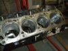
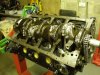
With the block back from boring and line-honing of the main bearings, it was cleaned and painted externally.
The valley stand pipes have been added (thanks Jac Mac fro the info), and I’ve still to add the mesh to keep any potential debris dropping down into the sump.
New cam bearing have also been installed. As they are all a different diameter 5 different mandrels sizes are required to fit them. As I didn’t have sufficient scraps of aluminum bar, I fitted the smallest first and progressively turned the mandrel down for each bearing.
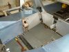
Whilst I waited for the a few other bits and the bearing to match my crank, I finished paneling the engine bay. The panel closest to the starter motor has to be kinked to give sufficient clearance. These will not be fitted once the rest of the plumbing is done, but made now whilst I have the access. New & potential Tornado builders should note that unless it has been changed recently; these panels are not part of the instructions/paneling kit.
Regards
Andy
The valley stand pipes have been added (thanks Jac Mac fro the info), and I’ve still to add the mesh to keep any potential debris dropping down into the sump.
New cam bearing have also been installed. As they are all a different diameter 5 different mandrels sizes are required to fit them. As I didn’t have sufficient scraps of aluminum bar, I fitted the smallest first and progressively turned the mandrel down for each bearing.
Whilst I waited for the a few other bits and the bearing to match my crank, I finished paneling the engine bay. The panel closest to the starter motor has to be kinked to give sufficient clearance. These will not be fitted once the rest of the plumbing is done, but made now whilst I have the access. New & potential Tornado builders should note that unless it has been changed recently; these panels are not part of the instructions/paneling kit.
Regards
Andy
Attachments
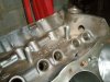
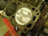
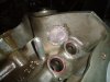
I’m building the engine with Edelbrock ‘Performer RPM’ cylinder heads & Keith Black high compression pistons. The heads are supposed to be 60cc combustion chambers, but these came out at 59cc when I measured them with a burette. There was no value given for the pistons, but I was looking for 10 – 10.5:1 To measure the pistons the perspex plate (pictured) has a known volume machined in specifically for this purpose.
After scaring myself with a fag packet calculation for the compression ratio (12:1:stunned") I decided I needed to do it properly on the old ‘confuser. After I’d sorter out decimal places!! the compression ratio came out to a more acceptable 10.6:1.
I decided I needed to do it properly on the old ‘confuser. After I’d sorter out decimal places!! the compression ratio came out to a more acceptable 10.6:1.
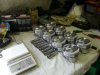
The pistons & rods have all been weighed. If this was an all out high revving race engine I’d be matching the assembly weights to within 2 grammes. As this engine isn’t, the cam has been selected to give power between 1500 & 6000rpm, I’ve matched the lightest pistons with the heaviest pins/rods as a compromise. Piston rings have been gapped to the piston manufacturer’s recommendation and are now ready for fitting.
Regards
Andy
After scaring myself with a fag packet calculation for the compression ratio (12:1:stunned
I decided I needed to do it properly on the old ‘confuser. After I’d sorter out decimal places!! the compression ratio came out to a more acceptable 10.6:1.The pistons & rods have all been weighed. If this was an all out high revving race engine I’d be matching the assembly weights to within 2 grammes. As this engine isn’t, the cam has been selected to give power between 1500 & 6000rpm, I’ve matched the lightest pistons with the heaviest pins/rods as a compromise. Piston rings have been gapped to the piston manufacturer’s recommendation and are now ready for fitting.
Regards
Andy
Attachments
Hi Simon
crankshaft, flywheel, clutch cover and TV damper have all been dynamically balanced, based on ther weight of the new piston & rod assemblies, so I shouldn't have any problems
Regards
Andy
crankshaft, flywheel, clutch cover and TV damper have all been dynamically balanced, based on ther weight of the new piston & rod assemblies, so I shouldn't have any problems
Regards
Andy
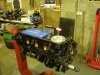
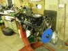
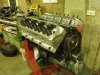
The cam timing has been now checked and found to be within 1 degree of the manufacturer’s recommendation – good enough for me. Stainless steel mesh has been added to the valley drains, which is held in place with epoxy resin.
All piston/rods fitted, although originally I managed to build up 3 rods with the pistons the wrong way round (the rods have a larger chamfer on one side of the big end to match the fillet radius on the crank) and the Spirol-Lock circlips are a right pain to remove.
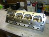
The heads are Edelbrock Performer RPM with the 1.9” inlet and 1.62 exhaust valves. Even though it says ‘performance straight from the box’ I pulled a couple of random valves to check seats etc and I must say the quality is excellent, especially fro the price. The valve stems are necked and the valves seats are nicely blended into the ports
Even with the raised crown pistons fitted, the piston/valve clearance was checked with modelling clay and there is plenty of clearance. The only annoying part is that the standard steel rockers foul on the larger spring retainer (although in fairness it does say this may be an issue in the small print of the cyl head instructions). I could grind them back, but I don’t like the idea of weakening them. A set of roller rockers is now on the shopping list, as well as a new set of push rods as hardened ones are required to work with the guide plates.
I’m now waiting for the front cover to come back from machining, before the sump can be fitted.
Regards
Andy
All piston/rods fitted, although originally I managed to build up 3 rods with the pistons the wrong way round (the rods have a larger chamfer on one side of the big end to match the fillet radius on the crank) and the Spirol-Lock circlips are a right pain to remove.
The heads are Edelbrock Performer RPM with the 1.9” inlet and 1.62 exhaust valves. Even though it says ‘performance straight from the box’ I pulled a couple of random valves to check seats etc and I must say the quality is excellent, especially fro the price. The valve stems are necked and the valves seats are nicely blended into the ports
Even with the raised crown pistons fitted, the piston/valve clearance was checked with modelling clay and there is plenty of clearance. The only annoying part is that the standard steel rockers foul on the larger spring retainer (although in fairness it does say this may be an issue in the small print of the cyl head instructions). I could grind them back, but I don’t like the idea of weakening them. A set of roller rockers is now on the shopping list, as well as a new set of push rods as hardened ones are required to work with the guide plates.
I’m now waiting for the front cover to come back from machining, before the sump can be fitted.
Regards
Andy
Attachments
The cam timing has been now checked and found to be within 1 degree of the manufacturer’s recommendation – good enough for me. Stainless steel mesh has been added to the valley drains, which is held in place with epoxy resin.
All piston/rods fitted, although originally I managed to build up 3 rods with the pistons the wrong way round (the rods have a larger chamfer on one side of the big end to match the fillet radius on the crank) and the Spirol-Lock circlips are a right pain to remove.
The heads are Edelbrock Performer RPM with the 1.9” inlet and 1.62 exhaust valves. Even though it says ‘performance straight from the box’ I pulled a couple of random valves to check seats etc and I must say the quality is excellent, especially fro the price. The valve stems are necked and the valves seats are nicely blended into the ports
Even with the raised crown pistons fitted, the piston/valve clearance was checked with modelling clay and there is plenty of clearance. The only annoying part is that the standard steel rockers foul on the larger spring retainer (although in fairness it does say this may be an issue in the small print of the cyl head instructions). I could grind them back, but I don’t like the idea of weakening them. A set of roller rockers is now on the shopping list, as well as a new set of push rods as hardened ones are required to work with the guide plates.
I’m now waiting for the front cover to come back from machining, before the sump can be fitted.
Regards
Andy
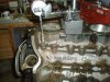
Looks like the lifter in picture number 3 may have a burr or two on the sides! :lipsrsealed:
In regard to your rocker arm problem - I have gotten away with running Lash Caps on the tops of the valves and longer pushrods. This was done in a racing class that required stock rocker-arms with no modifications.
A rather "Band-Aide" approach to your issue but it does work..
Hi Randy,
You got me all worried then about the on the tappet :laugh:. I justed needed a longer extension on the lifter, so I screwed a suitable tap into an old lifter body
I'll look into lash caps, but the issue then becomes sizing the push rods. A bit more investigation is required.
Thanks for the input and keep up the good job you and the other moderators in keeping this a great site
Regards
Andy
Hi Randy,
You got me all worried then about the on the tappet :laugh:. I justed needed a longer extension on the lifter, so I screwed a suitable tap into an old lifter body
I figured it must have been something like that - or - you had one HECKUVA high lift lobe there!!!
Good job checking it all out!
:thumbsup:
Andy
Just a quick one to say hi & nice to see the engine coming on.
Popped up to see Bryn & had agood chat. Bryn's car is a cracker, attention to detail really nice. Best of all he is that it is not too far from finishing post.
I am flat out on paneling still wnen time allows. New bulkhead finished, all cills & uprights finished, second battery tray built to accept a red top 40 as these are working well in some of our cars down here....only wish there were 48 hrs in a day.
Keep up the good work on engine & build.
ps no email at mo
Regards
KarlB:thumbsup:
Similar threads
- Replies
- 4
- Views
- 2K