Norfolk Tornado

Randy V

Moderator-Admin
Staff member
Admin
Lifetime Supporter
Hi Simon,

This had crossed my mind, but I've seen others use one-piece flanges with cross-over pipes. I can always get the hacksaw out later........

Regards
Andy

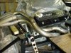
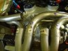
Like these from RCR;

Image053.jpg


Image054.jpg


IMG_1087.jpg
 
One down, seven to go :laugh:

However I suspect even this will need tweeking to get the rest of the pipes fitted!

Regards
Andy
 

Attachments

  • P4251195.jpg
    P4251195.jpg
    55.9 KB · Views: 712
  • P4251196.jpg
    P4251196.jpg
    59.5 KB · Views: 650
Second pipe now tacked together. There again, I’m sure that it will probably need tweaking as I fit more of the pipes. This is a lot harder than it looks and I think I’ve found the limit of my fabrication skills :cry:

I’ve had to reposition the anti-roll, as it was sitting below the collector. By moving it forward it’s given more clearance to the rear clam. The good news is that so far I’ve got good access onto the spark plugs

Regards
Andy
 

Attachments

  • P4251199.jpg
    P4251199.jpg
    50.1 KB · Views: 608
  • P4251200.jpg
    P4251200.jpg
    56.9 KB · Views: 608
  • P4251201.jpg
    P4251201.jpg
    56.8 KB · Views: 616

Ian Anderson

Lifetime Supporter
Hi Andy

Good to speak to you on Sunday at the show.

Another thing to try and "build in" is the ability to get nuts / bolts (Manifold to head) in and a spanner on them - I know on my set it is start at rear and work forwards or it's no go

Ian
 
Ian,
Yes it was good to put a face to the name & have a look around your car. I plan to use cap head bolts for the flanges onto the cylinder heads, as these allow more clearance to the actual header. Socket access is pretty good, but a selection of ‘wobble drives’ may be required.

Mark,
Wishful thinking! All you need is a few bends, a grinder and an ideal of where the pipes need to go. Easy (not!)

Simon,
The easiest way would have to been to design it all in CAD and then prepare a cut list. However I’m not that skilled and I’m working from a selection of mandrel bent pipes in 1.75” mild steel.

Regards
Andy
 

Terry Oxandale

Skinny Man
Andy, I admire anybody willing to fabricate headers. I've built two sets in the past, but nothing as elaborate as what I'll need for my current project (180 equal length), but the debate in my mind at the current time is, "do ya really need the 180 configuration?" None of the CamAm cars had it, so it does cause pause to ponder and study. Anyway, Good job!

Oh, BTW, are you using any of the Hooker alignment/weld rings on these joints. They're a Godsend at times if not.
 
Last edited:
Andy:
Headers are always a challenge, especially keeping the length while working in tight quarters. I have a set of alignment clamps that I use for welding, but I also use a large vise grip with two pieces of angle welded to the jaws, and the tubes line up perfectly.
I am looking forward to seeing your finished product, and your configuration around the collectors. One advantage you have is the stubs on your flange which allow you freedom of rotation when setting up your sweeps, sure is easier than trying to come directly out of the collector at the proper angle.
Cheers
Phil
 
Hi Terry
I’ve had some engine simulation done by a colleague at work to confirm my parts selection and more importantly predict the performance with the cam I’d selected. One of the iterations was without the cross-over exhaust and it shows a loss of 3hp at 6000rpm. Not a big deal, but for me a ’40 does not look right without a cross-over system.

I’ve not come across these Hooker alignment/weld rings, but a quick trawl of the web located them and they look a very useful product

Hi Phil,
I like your idea of a modified clamp with angle iron welded into the jaws. I currently use duct tape for the individual sections until they are approximately correct and then tack welds for a more permanent location

Regards
Andy
 

Terry Oxandale

Skinny Man
Thanks for that tidbit on the 180 vs non-180 HP study. I want to build some just as you're doing, but the deck is so low on my project that the top of the collectors must be no higher than the top of the wheel lip in order to avoid interference with the rear bodywork. To do that, both collectors must be on either side of the differential (instead of on top of it), which then means they are separated by about 10" (inside to inside). Everything I try to come up with for a crossover system is controlled by the now longer crossover tubes (which then mandates a longer minimum length for all the other tubes) if indeed I attain a true equal length system. What then happens is the short tubes now must have a lot of bends and sweeps to lengthen them to this minimum length. So I may do the rare thing and give up on the typical side-by-side collector/180º crossover exhaust headers and simply go 4-into-1 on each side.

Just curious if any of you guys have used a "same weight" methodology to ensure tube lengths are all the same. I'm rationalizing that if each tube is the exact same weight as all the other tubes, regardless of its individual shape (given all tubes use the exact same size tube and material), then each tube should in essence be the same centerline length. Does this sound reasonable?
 
Last edited:

Ian Anderson

Lifetime Supporter
Just curious if any of you guys have used a "same weight" methodology to ensure tube lengths are all the same. I'm rationalizing that if each tube is the exact same weight as all the other tubes, regardless of its individual shape (given all tubes use the exact same size tube and material), then each tube should in essence be the same centerline length. Does this sound reasonable?[/QUOTE]


Fill the pipe with water
Pour the water into a measuring cylinder
Same volume = same length

Ian
 
As well as the tank tape & spot welds to temporary hold the pipes, I knocked up a few simple clamps. The design is normally used for body work repairs (allows a butt repair with a 1mm gap for welding), but I’ve found them equally as useful in fabricating the exhaust system.
Regards
Andy
 

Attachments

  • P5081283.jpg
    P5081283.jpg
    44 KB · Views: 576
  • P5081285.jpg
    P5081285.jpg
    41.5 KB · Views: 529
A few more updates shots of the exhaust. Progress has been very slow, as I spend most of my time thinking. Running out of mandrel bends hasn’t helped. I also found that I could get hold of tighter 90° bends, which again has caused more re-planning.

I think I now know most of the pipes will run, but pipes 6 & 7 are the hardest to route, as they have to come in above and below pipes 2 & 3
Regards
Andy
 

Attachments

  • P5161299.jpg
    P5161299.jpg
    62.8 KB · Views: 621
  • P5161300.jpg
    P5161300.jpg
    45.8 KB · Views: 591
  • P5161301.jpg
    P5161301.jpg
    51 KB · Views: 630

Randy V

Moderator-Admin
Staff member
Admin
Lifetime Supporter
Interesting clamp design you have there...

The construction of headers is rarely easy. Making them into a cross-over system is quite a daunting task that takes an almost infinite amount of patience...

Soldier on!
 
Andy:
Looking good on the headers so far. You've set yourself up nicely with the stubs on the flanges which allows you to rotate as you fit tubes. Its really hard to fit to the flange opening directly and get the tube in the orientation thats needed.
I always use three tacks on all tubes, and you can anticipate a little shrinkage when you finish weld everything, but it looks like you have a good fit.
Terry's method of weighing the tubes works well, much easier than trying to find the centerline as you run a wire or tape through the tube.
I was curious as to what method you will use to finish the welding, how you expect the finish product to look etc.
It looks like you will have a nice system when completed.
Cheers
Phil
 
Hi Guys,
Thanks for the encouragement. My current thinking on finishing is to complete the welds with my trusty mig and then grind/linish the joints back. I’ll then send them off for ceramic coating, to be either finished in chrome or a satin black
Regards
Andy
 
Back
Top