Original Ignition amp

JimmyMac

Lifetime Supporter
Hi Peter,
Yes I can remember transistors and even crystal radio sets and I made my own batch of those expensive dual ballast resistors at one time for this set up. .:)
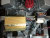
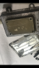
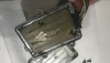
However nowadays, I believe that it might be a simple modern 8 cyl. Pertronix kit for me despite having a 35 litre box of Autolite transistorised parts.

The original system is obviously temperamental and very costly to run and these Autolite components will make good currency if I ever get around to swopping parts.
 

JimmyMac

Lifetime Supporter
Here you go Peter.
A bit akin to Rick's Boss scrap bin mentioned previously.

IMG_1322.jpg
 

Neil

Supporter
The Crane HI-6 capacitive discharge ignition gives multiple sparks while cranking the engine and a very powerful single spark when running. It also has an adjustable built-in rev limiter. I recommend it.
 

Attachments

  • Ignition Box.jpg
    Ignition Box.jpg
    94.3 KB · Views: 243

Peter Barnes

Supporter
Here you go Peter.
A bit akin to Rick's Boss scrap bin mentioned previously.

Hi James,, Yes, back in the day my Dad paid for my subscription to Practical Electronics, made similar circuits back then !

Nice box of bits, Will you use the regulator with your alternator ?

I agree best to use a modern set up, I thought I might be able to make it look original by adapting the parts , we will see. However it is good to know what was installed and how it worked.

A ballast resistor is for sale on e Bay, but expensive !

Thanks Peter
 

JimmyMac

Lifetime Supporter
Hi Peter,
Mark is our spark and we discussed my Pertronix option this week and he is getting back to me with a plan.
I have already bought the kit.
I want to use my XF distributor and fit all of the original parts to the chassis but these may be ornamental baggage in use.

Yes the Autolite stuff is expensive on eBay these days. And more so with the fake empty regulator boxes.
 
Last edited:

Peter Barnes

Supporter
Hi Peter,
Mark is our spark and we discussed my Pertronix option this week and he is getting back to me with a plan.
I have already bought the kit.
I want to use my XF distributor and fit all of the original parts to the chassis but these may be ornamental baggage in use.

Yes the Autolite stuff is expensive on eBay these days. And more so with the fake empty regulator boxes.

Hi James,
Pertronix seems to be the favoured option. However I doubt if I will find a XF distributor, hence the idea of using the Hi Po one I have.

Still curious as to what the "plug" on the outside of the amp is ?

Peter
 

Davidmgbv8

Supporter
The Crane HI-6 capacitive discharge ignition gives multiple sparks while cranking the engine and a very powerful single spark when running. It also has an adjustable built-in rev limiter. I recommend it.
I have run a HI -6 for 23 years on my MGB v8 and works really well, rev limiter saved me when at pet shifted and stuck full throttle in 3rd gear whilst entering the freeway!
 

Jim Rosenthal

Supporter
IIRC, the diagrams didn't have values on them, did they... so you would have to reverse engineer from an old one if you could read the resistor and cap values off them.... the other question is this: as an early solid-state ignition amplifier, it may not have been all that good to begin with. Were I to attempt this, I'd probably try to figure out a way to make it LOOK original, but have modern components inside it.
 

Peter Barnes

Supporter
IIRC, the diagrams didn't have values on them, did they... so you would have to reverse engineer from an old one if you could read the resistor and cap values off them.... the other question is this: as an early solid-state ignition amplifier, it may not have been all that good to begin with. Were I to attempt this, I'd probably try to figure out a way to make it LOOK original, but have modern components inside it.

Hi Jim , That is my thought, to put modern circuits in an old regulator box, I believe they were unreliable. and over complicated with the relay and double ballast resistor !
As James says above, the original parts will be there for "the look"
However I am interested in how it all worked in the 60's .

Still curious as to what the "plug" on the outside of the amp is ? (see Graham's 3 boxes above)

Best wishes, Peter.
 

JimmyMac

Lifetime Supporter
I think this thread is now way off-piste so apologies.
The amplifier is only one element of the ignition system and you will need to design, test and upgrade all of it.
If you fancy the idea of retrofitting electronic amplifier internals have a look at the dependable Ford '74 Duraspark ignition units. These amplifiers are everywhere and cheap enough to experiment with.
However you will also need to get the matching Duraspark distributor which is bigger than the HiPo unit because it generates a lot of heat. It also has vacuum advance. I believe the ballast resistor is just a thick wire.

This idea was offered by a good friend of mine.
 

Peter Barnes

Supporter
I think this thread is now way off-piste so apologies.
The amplifier is only one element of the ignition system and you will need to design, test and upgrade all of it.
If you fancy the idea of retrofitting electronic amplifier internals have a look at the dependable Ford '74 Duraspark ignition units. These amplifiers are everywhere and cheap enough to experiment with.
However you will also need to get the matching Duraspark distributor which is bigger than the HiPo unit because it generates a lot of heat. It also has vacuum advance. I believe the ballast resistor is just a thick wire.

This idea was offered by a good friend of mine.

Hi James, No apologies required. The opening question was faceted , and I am pleased to say I have received some useful info.

I have the detail for the original set up and now can explore how to graft in a modern system. It may not be possible to graft something into the original Amp box, I might have to hide a new box and just have the original parts on show .

I have 2 Hi Po distributors, 1 came with a Duraspark sensor, appears to be cobbled up and I do not know its origin ! I need to use a system compatible with my distributor.

Thanks for offering up your friends advice, all gratefully received

Peter
 

Rick Muck- Mark IV

GT40s Sponsor
Supporter
And was the original coil an Orange/ yellow top, 12 Volt ?
Yes, the original coil for transistor ignition was black with the "mustard top" however is a different part number with part number C3TF 12029 A and is not interchangeable with the standard coil. I had an NOS case of them some years back that I bought for almost nothing from a Mustang parts vendor who had bought them thinking they were the standard mustard top units.
 
There’s no Toroid in the GT40 amp module. It’s quite a sophisticated & refined circuit. Ford archives don’t even have any info on it (see attached image of their blueprint).
The back room tech boys at Dearborn designed & hand built these modules starting with a standard breakerless transistorised circuit but then modified/improved it to give a more accurate/stable output & better overall reliability.

Pics of what you find when you open one up are attached. You won’t believe how much time was spent removing the epoxy resin with a dental pick.

I’ve been working on reproducing this exact module for 2 years using all original components . I must have spent 3-4 months solid on this project. It’s coming together now.

I’d still like to find the original circuit diagram if anyone can think what they used. The circuit diagram in the SAE Papers that Jim R posted is a simplified version of the module circuit board but it isn’t complete and has no component values shown.
We have the values of all components from the modules but I’d still like to compare them against the original schematic.

As Graham E states, the ‘knob‘ is actually a plug. I often get these 2 things mixed up myself !
 

Attachments

  • 0EE0925C-A871-46FC-8470-60B569586F42.png
    0EE0925C-A871-46FC-8470-60B569586F42.png
    1.3 MB · Views: 190
  • 2A7C6967-E15F-474A-A91C-F21A3B8045D0.png
    2A7C6967-E15F-474A-A91C-F21A3B8045D0.png
    2.7 MB · Views: 214
  • CC600AB8-97BA-407B-B7FF-5217D8F361F7.png
    CC600AB8-97BA-407B-B7FF-5217D8F361F7.png
    768.9 KB · Views: 207
  • 60C507E1-164F-4928-B649-D415C382A179.jpeg
    60C507E1-164F-4928-B649-D415C382A179.jpeg
    52.1 KB · Views: 191
  • 2BD88F86-AB69-4D2A-8033-6FF0C3DA99D9.jpeg
    2BD88F86-AB69-4D2A-8033-6FF0C3DA99D9.jpeg
    38.3 KB · Views: 193
  • E754496D-C500-4DAE-B312-0176C4927FC2.png
    E754496D-C500-4DAE-B312-0176C4927FC2.png
    293.8 KB · Views: 203

Peter Barnes

Supporter
There’s no Toroid in the GT40 amp module. It’s quite a sophisticated & refined circuit. Ford archives don’t even have any info on it (see attached image of their blueprint).
The back room tech boys at Dearborn designed & hand built these modules starting with a standard breakerless transistorised circuit but then modified/improved it to give a more accurate/stable output & better overall reliability.

Pics of what you find when you open one up are attached. You won’t believe how much time was spent removing the epoxy resin with a dental pick.

I’ve been working on reproducing this exact module for 2 years using all original components . I must have spent 3-4 months solid on this project. It’s coming together now.

I’d still like to find the original circuit diagram if anyone can think what they used. The circuit diagram in the SAE Papers that Jim R posted is a simplified version of the module circuit board but it isn’t complete and has no component values shown.
We have the values of all components from the modules but I’d still like to compare them against the original schematic.

As Graham E states, the ‘knob‘ is actually a plug. I often get these 2 things mixed up myself !

Hi Paul,
Thank you for the very interesting input. I am intrigued to see a photo of the "plug" and what does it cover ?

If you have removed the printed circuit board you should be able to trace all the connections to to make a diagram.

Reading your thoughts above maybe there is no original diagram . I think the system used on the fords of the day used was the amp mentioned above by Rick . This has one power transistor where as yours had 2 under the top cover.

Best wishes, Peter
 
Back
Top