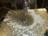
Wow, I never thought to use one of those drills. I just have been using cheap hole saws in the milling machine. I bet they make a more accurate cut!!

You are using an out of date browser. It may not display this or other websites correctly.
You should upgrade or use an alternative browser.
You should upgrade or use an alternative browser.
Ozi 206 sp
- Thread starter Jim C
- Start date
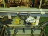
Very accurate Dave.
I find hole saws hurt my drilling chucks when they snag up.
It was $66 Aust and it fits a collet chuck.
Jim
I find hole saws hurt my drilling chucks when they snag up.
It was $66 Aust and it fits a collet chuck.
Jim
I made an adapter that goes right into a 5/8 collet and the hole saw threads onto that,so everything is held more solidly.However this looks much better!
I haven't posted because I didn't feel I had done that much but after looking through the photos I realize I have done more than I thought.
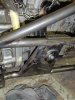
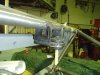
Engine and suspension mounts.
I use a suspension bush for the mounts, I used them on my 40 and they cost $24.
The bush presses into the cup that I machined out of a bar,it has a 2mm wall.
The brackets mounted on the block are sheet steel.
Engine and suspension mounts.
I use a suspension bush for the mounts, I used them on my 40 and they cost $24.
The bush presses into the cup that I machined out of a bar,it has a 2mm wall.
The brackets mounted on the block are sheet steel.
Attachments
Last edited:
suspension mounts
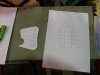
A good trick I use when making brackets.
I cad it then print to scale, spray glue the back and stick it to the job, then dril cut ect.
Peel it of you are done.
A good trick I use when making brackets.
I cad it then print to scale, spray glue the back and stick it to the job, then dril cut ect.
Peel it of you are done.
Attachments
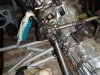
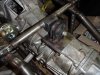
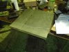
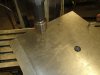
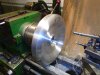
I made the conversion plate out of 33mm alloy plate.
I only measured the 2 dowl pins on the motor 2 on the box and their relationship to the crank C/L.
The other holes where transfer punched.
I had to machine a few areas slave cyl and crank sensor.
In the pics I machined a hole for a spigot bearing,this allows me to check the fit of the box on the dowls before transfer punching the gearbox bolts
I just band sawed the plate then cleaned it on the linisher.
The inside hole I cut through the starter hoop to cut the waist out.
I cleaned the inside hole with a router using a template.
Attachments
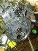
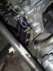
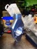
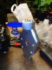
Gearbox
EBAY $250
Subaru 2.5 lt turbo liberty 5speed.
I removed the extension housing ,rear diff ,transfer gears and bined them.
The centre housing I have left the shift casting and machined off that that is not required.
The bearing hole I will plug, I can buy a splined sleeve that goue onto the lower shaft and this will make it drive out of the front diff.
The rear I have made a sheet cover that will get 2 m6 bolts and some sealer adhesive.
The diff I will weld the centre as it will be track only.
Attachments
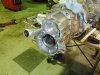
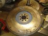
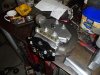
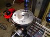
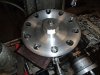
Know this I didn't believe, I had to check it twice.
I was given a Subaru flywheel for setup purposes.
The centre hole was to small so I machined it out to 41mm to suit the Nissan crank.
It has the same PCD as the Nissan,With the 33 mm conversion plate the starter and spigot bearing lined up perfect.
I will buy a light one when its required.
I will use a standard subaru clutch, it wont need any more than that.
Attachments
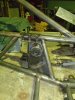
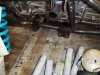
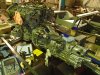
In an earlier post I made sheet metal uprights.
The rear I was happy with but the front I never was.
I could also see issues fitting the steering arm.
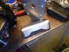
With the scrap from the center of the gearbox conversion plate I made 2 front uprights and I had to make caliper brackets as well.
The caliper has a S/Steel bracket to hold it to the upright,as per the sheet pattern in pic 4.
The steering arm will be sheet ,one in between the top ball joint mount and one on top.
All the radius on the edges of the uprights I did in the mill just using router bits (tungsten carbide).
The rear I was happy with but the front I never was.
I could also see issues fitting the steering arm.
With the scrap from the center of the gearbox conversion plate I made 2 front uprights and I had to make caliper brackets as well.
The caliper has a S/Steel bracket to hold it to the upright,as per the sheet pattern in pic 4.
The steering arm will be sheet ,one in between the top ball joint mount and one on top.
All the radius on the edges of the uprights I did in the mill just using router bits (tungsten carbide).
Attachments
I want center lock wheels because its period, I am happy to forgo spinners for nut just because its practical.
The flanges I machined out of 4140 chromemoly, the nuts a 6061 t6.
The pin drives will be the heads of m12 alan bolts.
The flanges I machined out of 4140 chromemoly, the nuts a 6061 t6.
The pin drives will be the heads of m12 alan bolts.
Attachments
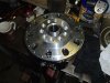
Wheels
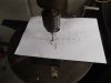
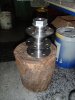
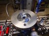
Pic 1 I punch a hole in the billet to center on the table, the 2 outer are just for mounting.
Pic 2 face for the arbor.
Pic 3 counter bore for the center lock.
Where the drive pins go I put 5 m10 threads in instead.
Pic 1 I punch a hole in the billet to center on the table, the 2 outer are just for mounting.
Pic 2 face for the arbor.
Pic 3 counter bore for the center lock.
Where the drive pins go I put 5 m10 threads in instead.
Attachments
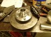
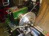
I mount it to an arbor then do all the profiling on the front.
I then turn the arbor around and remount and do all the rear face.
The wheel and rim is 5kg.
Thats it for the moment, suspension arms and rack after the wheels are done.
Jim
I then turn the arbor around and remount and do all the rear face.
The wheel and rim is 5kg.
Thats it for the moment, suspension arms and rack after the wheels are done.
Jim
Attachments
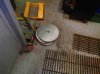
Outers as in rims I presume.
Alloy spun, they weight nothing.
13" x 10 on rear
13" x 7.5-8.5 on front
It will be on slicks
Alloy spun, they weight nothing.
13" x 10 on rear
13" x 7.5-8.5 on front
It will be on slicks
Clayton
Supporter
Will you be welding a ring into the outer to bolt the centre to ??Outers as in rims I presume.
Alloy spun, they weight nothing.
13" x 10 on rear
13" x 7.5-8.5 on front
It will be on slicks
Hey Chris
knowing Jim, he probably free hand the radius and got all four within 0.005" of each other :stunned:
Clayton
nice work Jim
how did you do the oval holes in the face?
how did you machine the rounded profile on the face?
chris
I machined angles across the face,using a few fixed angles as in the angle running into the center is 55deg and the one on the outside edge is 48deg .
In cad I drew the cut angles on the profile drawing then that gave me the trajectory entry/exit on the top face and the side face.
I use router bits on the mill and the job in the rotary table, I run at 1300rpm and you would be shocked at how quick it comes of once you are set up.
Eg If I want a 45deg angle I use a 45 router bit,or if I need 55 deg I use a 45 and only pull 10 on the head it makes it faster.
Sorry to bore you guys with details but Chris and I have the same milling machine.
When that was done I used a disk sander while in the lathe and knock all the corners down,then clean up with emery.
I also have a pattern that I keep fitting into the rim to check as you go.
If I can get them all fairly close I will be happy,you can only look at one at a time so any small differences will go unnoticed.
The slots are done in the mill on the rotary table, its actually an upside down triangle with radius corners
It is 3 holes and some milling.
I use a 25mm and 22mm router bits for the holes and a 22 mill tool for the milling
Its a bit of jerking around to a point I should have just made them slots.
jim
Last edited:
Similar threads
- Replies
- 4
- Views
- 470
- Replies
- 8
- Views
- 1K
- Replies
- 17
- Views
- 2K