Randy Folsom
Supporter
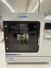
Just bought a Bambu H2D. It will take weeks, not days. Two heads won’t make any difference. Going to start with something manageable such as the nostril.Do you have a 3D printer that can do this? I have a customer who has one, but I still think it might take 2 days, even with 2 heads