
I am buiding a rear engined car that is going to be optimized for autocrossing. Pictures will follow.What my question is......when you are running an independent rear suspension is there any reason to put caster in the rear uprights? I guess if you broke something it would tend to still go straight but as far as handling goes would there be any advantages or disadvantages to it?Lets hear from the racers in the crowd as well as the street builders.

You are using an out of date browser. It may not display this or other websites correctly.
You should upgrade or use an alternative browser.
You should upgrade or use an alternative browser.
rear suspension setup
- Thread starter egoman
- Start date
Depends on the geometry, the original Gt40s had quite a bit of castor 8 degrees or more.
Helped with bumpsteer and maybe with lift under braking.
Dave
Helped with bumpsteer and maybe with lift under braking.
Dave
That sort of leads me to the next question. Is the gt40 rear suspension a good design for the tires of today. And is it still a competitive basic design overall.
I had not thought about using caster to control braking forces.We used to do this all the time with the dirt track modifieds on the front end. Because we used a solid rear axle it never occurred to me.
Any more responses?
I had not thought about using caster to control braking forces.We used to do this all the time with the dirt track modifieds on the front end. Because we used a solid rear axle it never occurred to me.
Any more responses?
For anti-squat/anti-lift on the rear, it's not the angle of the hub carrier but the angle of the trailing arm and radius arm pickup points that control the forces.
Ross Nicol
GT40s Supporter
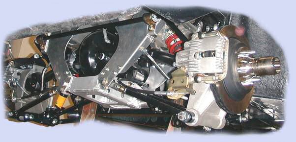
The rear suspension on my car is the same set up as the original GT40.
1/ lower reversed wishbone ( this means there is a spherical bearing at the chassis end which allows fore and aft movement of the wishbone)
2/ A top link ( single adjustable length rod)
3/ Upper and lower Trailing arms, radius arms or whatever name you have for them, ( from rear bulkhead back to upright, both with adjustable length)
The top link is adjusted to alter camber but the most difficult set up procedure is to control the dynamic Toe change as the suspension moves.
As the suspension moves the trailing arms are getting shorter and longer and this causes the dynamic toe to change. What I found is that by adjusting the length of the 2 trailing arms to set a positive caster angle on the upright I could take the suspension through it's full travel and the toe would stay constant.
Modern tyres no problem as long as suspension is adjusted to make full use of them.
Ross
Holy crap I havent worked on this in a long time and went even longer without any posts. I did say that I was posting on locostusa but I just learned how to do links.
LocostUSA.com | View topic - The locost formula for a slalom/track car. Egomans build.
LocostUSA.com | View topic - The locost formula for a slalom/track car. Egomans build.
The rear suspension on my car is the same set up as the original GT40.
1/ lower reversed wishbone ( this means there is a spherical bearing at the chassis end which allows fore and aft movement of the wishbone)
2/ A top link ( single adjustable length rod)
3/ Upper and lower Trailing arms, radius arms or whatever name you have for them, ( from rear bulkhead back to upright, both with adjustable length)
The top link is adjusted to alter camber but the most difficult set up procedure is to control the dynamic Toe change as the suspension moves.
As the suspension moves the trailing arms are getting shorter and longer and this causes the dynamic toe to change. What I found is that by adjusting the length of the 2 trailing arms to set a positive caster angle on the upright I could take the suspension through it's full travel and the toe would stay constant.
Modern tyres no problem as long as suspension is adjusted to make full use of them.
Ross
I accept this means that these principles also apply to the front suspension?
Terry Oxandale
Skinny Man
I accept this means that these principles also apply to the front suspension?
I would say no due largely to the difference in the way the front upright is controlled versus the rear. The geometric relationship of both control arms to the tie rod is what determines the front's bump steer characteristics (no tie rod exists at the rear - unless you have a C5/6 rear suspension or such)
Egoman:
I second Terry's no, and would add that the addition of the tie rod to the front upright introduces another radius component to the mix. The upper and lower front wishbones form a combined radius at the upright which must be duplicated by the tie rod in order to minimize bump steer in the front.
On the rear it is most important what Ross said about the inner pivot at the lower wishbone. The radius rods do move in an arc forming a radius, the upright essentially moves up and down in a slight arc as viewed from the side (Elevation), and as Ross said this will introduce bump as the radius rods pull and push the upright as the suspension goes thru its travel binding the inner mount. Also it is important to mention that the front mounting points of the tie rods do not simply rotate around the mounting bolts, but have have a slight rotation 90 deg to the mount axis, so a bushing here would bind your suspension and cause problems. The addition of positive caster in the rear uprights definitely greatly improves toe steer at the rear. I am running 5 deg. positive caster and there is negligible toe steer. This also may cause a slight rotation of the inner mount at the lower wishbone mount so most good setups have a spherical bearing at that point. One last item is that shocks mounted to the rear setups such as this need to have spherical ends as there is generally some front to rear offset in the mounts and as the suspension travels they will also bind if fitted with bushings.
A lot to think about for sure, but easily sorted out with the right components and geometry.
Hope some of this helps.
Cheers
Phil
Ummm.....I would guess that you guys didnt look at the link. The car is allmost complete and was more of a packaging exercise to see what I could get away with.
Look , you will like.
Look , you will like.
Terry Oxandale
Skinny Man
I've been observing all the posts here, and don't doubt the advice about caster reducing the bumpsteer effects, but I cannot bring myself to understand the geometry of this.
My lack of understanding stems from my perception that the ONLY thing controling the bumpsteer is the geometry between the lower transverse arm, and the lower trailing arm. Any pull/push by the trailing arm (as it swings a few degrees up/down) will cock the upright toe in/out, regardless of what the upper transverse link or upper trailing arm is doing. Is this not correct?
If so, then the best my mind can come up with is perhaps the effect of bump is diminished by the cosine of the amount of caster, but at even 20º caster, that's a pretty insignificant reduction. Then I thought about how increased caster reduces the angle of the lower trailing arm as the front lower bearing at the upright goes up while simultaneously the lower rear bearing gets closer to the ground (but again, it would need to be a significant amount), which gets the trailing arm closer to "horizontal" where the bump is reduce (if anti-squat is built in), but then squat starts in.
I also understand the placement of the bearing at the front of the trailing arm has a huge impact on bump (horizontal and aligned with the transverse link inner bearing would create no bump at all because the entire lower assembly rotates on an axis parallel to the chassis centerline, but then you've no anti-squat (as well as some other mounting and logistical issues). In all the designs I've studied (really, not much of a study which is based on photos), this is not ever the case, so some compromise of lateral and vertical placement of the front bearing becomes a best compromise (isn't everything automotive a compromise!)
So if the posted adjustments/results are correct, and I don't doubt they are, what piece am I not understanding?
Terry:
It is confusing for sure. The lower inverted wishbone as it mounts to the upright is relegated to one pivoting axis only, the upright can't twist in the cross mount for obvious reasons. This being the case the only toe, in or out, must come from fore and aft lower wishbone movement.
A lot of the toe comes from anti dive as the inner mounts are at different heights. The lower radius rod has a higher mounting point than the upper, and as you swing thru suspension travel the radii of the radius rods push and pull the upright and since its fixed at the bottom it travels in a radius created by the inner spherical bearing (if there is one), and the front lower radius rod mount. At ride height to full compression the lower rod pushes back usually creating toe out, eventually the toe will reverse its travel and the rod will pull inward as the suspension is compressed more but is usually limited by shock travel. In full droop usually there is toe in.
Adding caster essentially creates a pre-rotational set in the upright. The upright tends to try to rotate towards negative caster during bump, you lose caster, but it cancels the toe steer substantially. As viewed in elevation the upright swings in an arc and not straight up and down.
If the lower connection at the upright was a ball joint, and you had a tie rod this could be more easily dealt with.
I can tell you that a long time ago it made no sense to me also, but it does work. The saving factor is the fact that there is not a great amount of suspension movement as in a regular road car. My chassis has 4 1/2" travel, and there is almost zero toe steer in that travel, take off the shock and work the suspension and there is a lot of toe in the extremes of travel.
cheers
Phil
It might help to understand this concept if you make a model out of welding rod or coathanger wire for the links and an "upright" out of cardboard or whatever. That way you can setup extreme amounts of caster and trailing link angles and watch the steering effects it causes as the wheels rise and fall.You will see how the upright twists (toes) in and out depending upon how much caster is setup and how different link angles and locations affect the change. I did this for friends that could not visualize how the geometry works in a multilink rear suspension.
YouTube - MyEgoman's Channel
A few videos for you guys to look at.
A few videos for you guys to look at.
Howard Jones
Supporter
I will suggest a book that I have found very useful. I am sure that others will have their favorites as there are several good ones.
Amazon.com: Chassis Engineering HP1055 (0075478010554): Herb Adams: Books
As you construct your chassis, clearly mark the centerline. You will need it later when you begin to adjust your suspension. None of this stuff is high level math or rocket science. It just takes a little basic understanding of what is going on as the car loads and unloads in a corner, under braking and power.
The basis of all this is, everything (all the suspension mounts points as well as steering angle) are moving around on their individual arcs and the idea is to keep this from changing the tire contact patch relationship to the centerline of the chassis as they all do so.
As it is with everthing in life there is a lot of compromise going on. The rear caster issue is a good one. On a cart for example with a solid chassis, and no suspension movement other that it's designed flex and tire compliance, caster per se isn't necessary (be kind cart racers you get the point).
It is very important to control toe (goal= 0 rear bump steer) at the rear of a car with independent rear suspension that uses trailing arms like a GT40 so you put in positive caster to offset the changing EFFECTIVE trailing arm lenghts. All of this, and quite a lot more, is done to keep the rear tires contact patch as square to the road as possible while everthing else is trying to rotate it in three axes.
The front of the car has the added effect of steering and it's related set of bumpsteer issues.
Last edited:
If you have 2 lower lateral links instead of an inverted A arm you will not have any bump steer in the rear.
When you do put caster it will adjust your squat anti squat with no effect on bump steer.
Jim
When you do put caster it will adjust your squat anti squat with no effect on bump steer.
Jim
Jim,
first sentence is correct whilst lateral links are co planar
have you considered that when you apply caster the 2 lateral links are no longer
co planar ????
first sentence is correct whilst lateral links are co planar
have you considered that when you apply caster the 2 lateral links are no longer
co planar ????
Jim,
first sentence is correct whilst lateral links are co planar
have you considered that when you apply caster the 2 lateral links are no longer
co planar ????
When I designed the rear suspension for our Cobra replicas, I "castor'd" the hub carrier (and the inner mounts for lower radius arms) but it wasn't for any bump-steer consideration. I simply wanted to maximize the length of the upper trailing arm, the length of which was space limited by the presence of the darn driver...
I've noticed that McLaren, for example, went away from reversed lower a-arm in favor of parallel lower link rear suspension location(with single upper link and U/L trailing arms) on the M8F and again on the M20. And I can't recall (m)any modern rear racecar suspensions using the reversed lower a-arm design(alone) to locate the bottom of the rear upright.
Am I correct in assuming the reversed lower a-arm design is inferior to to parallel lower links in this style rear suspension, esp. when modern wide tires are used? When designing this style of independent rear suspension, is there any advantage to using the lower reversed a-arm linkage(vs. parallel lower links) to the rear upright(other than period correctness)?
Hypothetically, if one were to try to replace a lower reversed a-arm linkage with parallel lower links, would it be necessary to change anything else about the other parts of the rear suspension(i.e., upper single link, U/L trailing links, etc.)?
Jack
Similar threads
- Replies
- 4
- Views
- 954
- Replies
- 10
- Views
- 994
- Replies
- 4
- Views
- 3K