Scotts build thread

Scott,

Perhaps you could camouflage your unsightly “bump” with the Big Honkin' Fin (BHF) that must be sported by LeMans LMP1's and that the Scuderia Cameron Glickenhaus SCG 003 has on its rear deck.

SCG-003-Competizione-rear-quarter.jpg


2015-Audi-R18-e-tron-quattro-3.jpg


True, these cars have no bumps to hide, but the BHF can do wonders for hiding the, err, less desireable lines we have . . .

Les :)
 
Work continues to try to find a good looking way to incorporate the clearance needed for the intake.
I'm on my 4th variation now and still not very excited about it.

Stretchy fabric method- hmmm. needs something

http://i7.photobucket.com/albums/y251/scooter350z/Mobile%20Uploads/
2015-09/20150929_140846_zps473wbig8.jpg

(snip)
Awesome work, Scott

You noted difficulty in retaining the existing profile whilst clearing the intake, so how about eliding the polycarbonate cover instead? Perhaps leave it open, like the blowers on many front-mount motors, or does the interference extend to more than just that rear-window area?

2c
 

Howard Jones

Supporter
Some ideas
 

Attachments

  • sebring3.jpg
    sebring3.jpg
    132.4 KB · Views: 279
  • vintage-monterey-historics-1994-exhibition-porsche-962-al-holbert-s-imsa-lowenbrau.jpg
    vintage-monterey-historics-1994-exhibition-porsche-962-al-holbert-s-imsa-lowenbrau.jpg
    165.7 KB · Views: 289
  • Porsche_962_119_rear.jpg
    Porsche_962_119_rear.jpg
    879.2 KB · Views: 315
  • 1989-busby-porsche-962-68-daytona.jpg
    1989-busby-porsche-962-68-daytona.jpg
    157 KB · Views: 375
20150929_140846_zps473wbig8.jpg
[/URL]

Cardboard layout. Reverse scoop with layered alum fins on exit. I like, but not in this variation.


I through in the towel last night and broke down and bought a scoop that is nearly exact to my last pic. Will have something solid to mock up more stuff when that gets here in a couple weeks.
So, back off of body work and back to mechanicals!

I like your direction with the layered fins. What if you had air inlets on each side of of the area in front of the fins? This could allow a transition from that area down to the body. Not sure I am explaining it well... but I can see it in my fragile mind.[/QUOTE]

I think I am following ya, and was looking at something like that. The problem I was running into it was it makes the front roof opening look weird. I havn't given up on the idea though.
 
Scott,

Perhaps you could camouflage your unsightly “bump” with the Big Honkin' Fin (BHF) that must be sported by LeMans LMP1's and that the Scuderia Cameron Glickenhaus SCG 003 has on its rear deck.

SCG-003-Competizione-rear-quarter.jpg


2015-Audi-R18-e-tron-quattro-3.jpg


True, these cars have no bumps to hide, but the BHF can do wonders for hiding the, err, less desireable lines we have . . .

Les :)

I did originally start with a center fin idea. I didn't do much refining to it though, as this clearancing would still need to be done with a bubble or scoop. Once this is figured, I can start toying with the center fin again.
 
Awesome work, Scott

You noted difficulty in retaining the existing profile whilst clearing the intake, so how about eliding the polycarbonate cover instead? Perhaps leave it open, like the blowers on many front-mount motors, or does the interference extend to more than just that rear-window area?

2c

Tossed this idea around also. Would really like to leave the section open or viewable, but i would have to cut so far up to see the whole intake, there would be hardly any structure to the center of the rear clam and it would be very flexible.
 
Some ideas

Thanks Howard. One thing of note on those cars, is the lack of a roof inlet also. Plus the extentions behind the rear tires that elongate the body to bring some balance back. I would like the scoop to face forward like in your pics, but it really clashed with the existing roof inlet (which I really like) and didn't look right with the designs I tried.
Elongating the body will be harder than originally thought. Will need to be very creative with how it hinges.
 
Hey Scott, I really like the reversed scoop. It really flows well with the line of the car. What if you blended the back of the scoop with the rear of the roof tunnel to create continuity there? I think the line of the car might even improve overall and definitely not look 'tacked on tacky'.
 
Hey Scott, I really like the reversed scoop. It really flows well with the line of the car. What if you blended the back of the scoop with the rear of the roof tunnel to create continuity there? I think the line of the car might even improve overall and definitely not look 'tacked on tacky'.

Thats the plan. To mold the final product in. I came up with a couple different ideas that might look cool. Scoop I bought won't be here for a couple weeks though. It is very close in design to the cardboard one I made in the pics.
I should be getting the rest of the water/air intercooler system tomorrow and have the power e-brake to set up now too, so I have lots to do waiting for it. Also have the rest of the parts for the manifold and can finish it off.
 
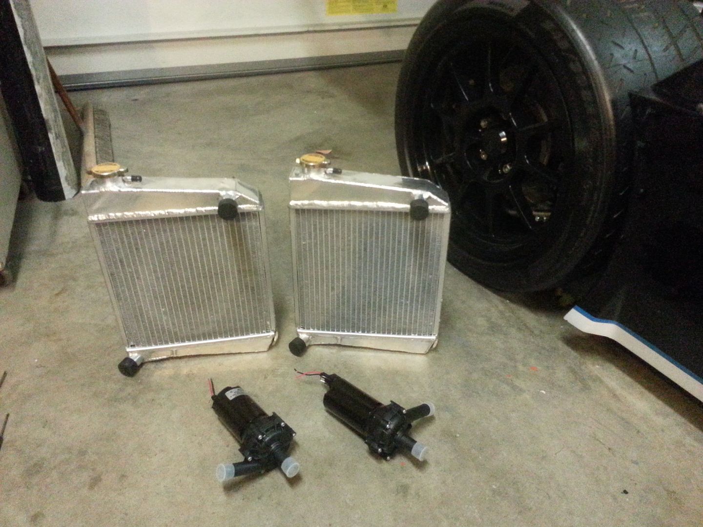
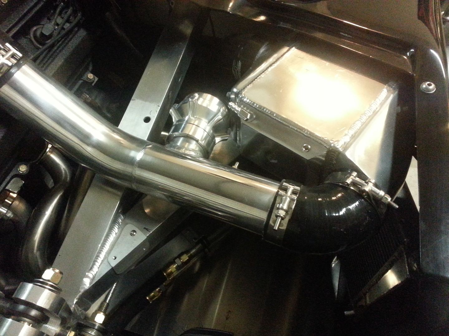
Finally got my intercooler heat exchangers. They are supposed to fit an early Mini Cooper and were only $55 each!! Yup, $110 for the pair new with a 1.3 bar pressure too. Also, two bosch water pumps that flow roughly 8gpm. Each turbo gets its own pump and heat exchanger. Way overkill for my boost levels, but, I really like the symmetry of each side identical and saved me from more plumbing to cross plumb both into one system.


Since the water/air intercoolers are now the top of the system, I had to come up with a way to fill and purge the air from the system. While puckered up abit drilling these holes in the intercooler end caps, I have one air escape hole, just remove the plug, and one fill hole that will go to a small motorcycle brake reservour that will attach to the side of the upright bars. Since there will be no pressure in the system, I can simply keep the reservour topped off and it will self purge any air.


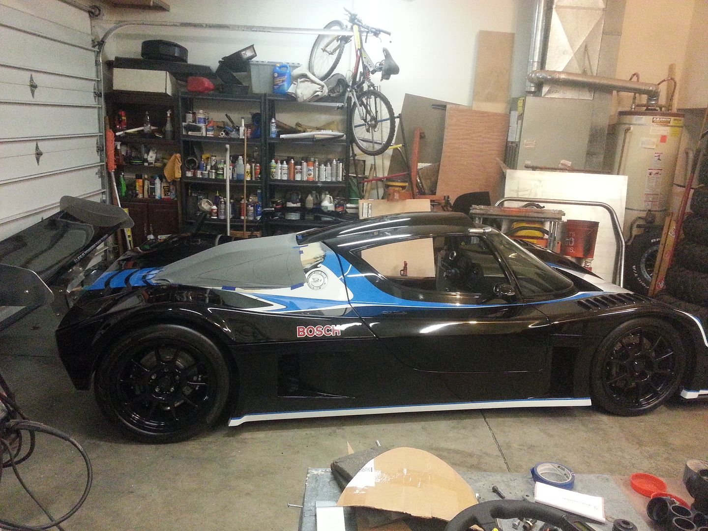
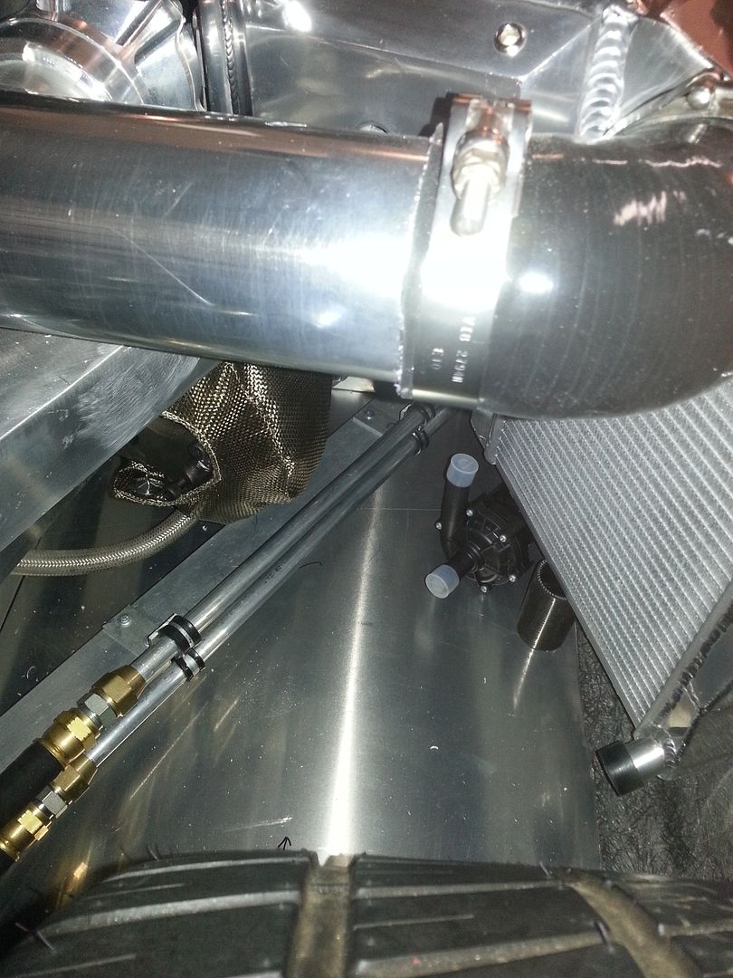
Need to make the mounts for the he still, but I am amased at how much room I actually have left considering the complexity of the system as a whole. Lots of hours of staring at it coming up with a plan, but it is all coming together now in symmetry and cleanliness.


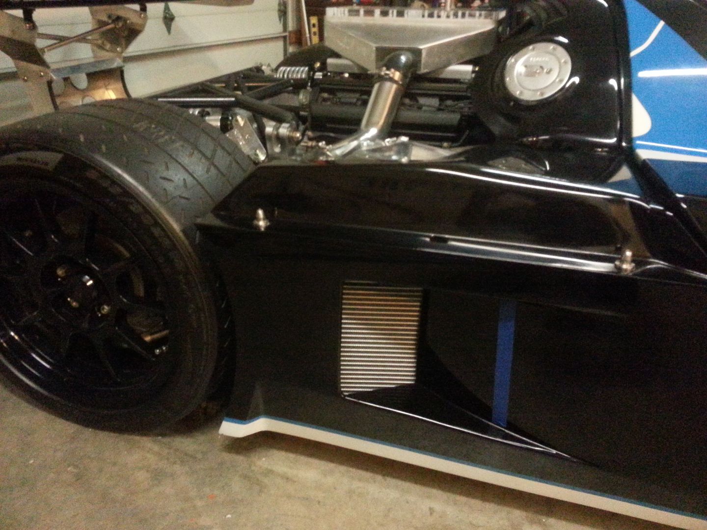
Since my side openings were already raised in height, I do not need to change that. But the blue tape marks how long I will need to cut out to expose the entire core to airflow. Not 100% set on the exact exterior design, but just happy I found a he that fits the parameters that works.


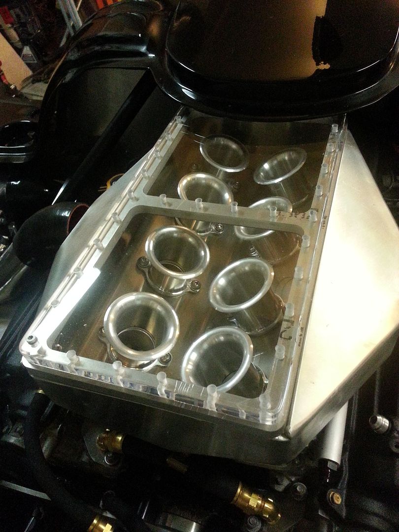
One more with plastic and flange completely drilled. I pulled a real dip shit move while tapping the very first hole in the flange. I usually put the tap in the drill and make easy work of it. Well, while doing the very first hole I said in my mind "whatever you do, do not break the tap off in the hole". Literally the second I completed that sentence in my head, the tap broke off in the hole. After 30 minutes trying to extract it, I just can't get it. It is harder than any drill bit, so drilling it out for a helicoil is ending up in dulled bits. I am afraid my last option is to cut the piece out, and weld it back up and grind smooth. Ugh. Tapped all of the rest by hand and it went smoothly.
Since the acrylic has a pretty high expansion rate with heat, I had to make the holes in the acrylic larger than the bolt size. A piece of foam will seal acrylic to the flange, and will have self sealing washers under head of bolts. Hoping this will be enough to keep from snapping bolts off. I will need to get fresh air running over the top of the acrylic to keep as cool as possible. Luckily, since it will never see vacuum in the plenum due to the itb's, I would only need to worry about boost pressure if the top becomes soft and wants to balloon. I also have some phenolic that is a great isolator from heat you can use as gaskets. Will need to get them water jetted out, but they are all the same and that should keep a little more heat out of the plenum.

 
Last edited:
That box looks fantastic. Have you thought of just making a cutout and leave the box exposed?

I have thought about it, but the angles don't even come close to matching, plus you still wouldn't be able to see all of the manifold unless I redesigned the top of the rear clam and made it go straight across instead of the continuation of the roof line. Not sure that makes any sense, my brain is baked from a long hard day at work. Lol.
 
Got the little motorcycle brake fluid reservoirs today. Will just mount on the bar there and they will act as a fill tank for the intercooler set up. Don't like the fact the hose covers part of the bov, but not much choice since line has to go up hill.


Header tank placement and overflow tank. I repurposed one of the e-brake brackets (that I couldn't use) to hold the overflow tank. Looks like it was made for it, haha.
Header tank will be raised a couple inches from the pic. Made a heat shield for the overflow tank also, that will get covered in the dei gold reflective material.

 
I dig the intake cover! Looks bitchin.

Just hope it doesn't pop like the last one I saw. Had some fuel build up in the intake, went to crank it over and BAMM!! Backfired, bent a rod and shot the intake straight up and took the hood out with it. Kinda scary actually.

I have a pic of one of the bolts logged 1/2" into the steel hood.

I was going to put a burst plate in it, until I remembered the throttle plates and injectors are below the plenum and not at the entrance of it. Even in an intake backfire the plenum will not see a pressurization, only under the throttle blade.
That 3/4" thick acrylic should be nearly indestructible, so I am most worried about expansion of it and shearing my end or corner bolts. I also have some 1/4" alum rod that I will be bracing the inside of the intake like pillars inside of it. So pretty much any precaution or scenario I could come up, I have tried to engineer around.
Now an intake backfire with lingering flames, will put me up shit creek. :shout: Haha
 
Scott? What ecu do you plan to use? I see you have distributors still? How old school of you.

I am still a little up in the air as far as my final ecu choice. I have a haltech e6x right now and harness. It is supposed to have a base map loaded already.
I was leaning towards a megasquirt, but after much researching, it sounds like the interface is tough to learn and it also isn't a favorite of my local tuner because of that. The extra cost to tune it will probably negate the initial lower purchase price. I am pretty sure I will go with a haltec platinum sport 1000 and make a new harness. I am familiar with the haltech interface and since your drivability tuning can take 8-10hrs to get perfect, I can just have my power tuning done and take care of the drivability myself.

Since you are doing a 1uz also, I am selling the e6x and harness, the original billet intake with throttle bodies, the intercoolers, and turbos and will make you a great deal on the package if you are interested. All are new. I'd go $2200 for the package.

As far as keeping the distributors, I will wait to make the decision once motor is out to be built. I have yet to fully investigate which way will be best for the ignition system. Which ever way will reliably get me to 10k rpm will be the winner! Lol. :thumbsup:
 
I have a megasquirted hot rod Porsche 3.9l motor. The interface really isn't that bad, and it is a good way to really know what's going on with your EFI. But if you don't have time to learn and you need local tuning, maybe it isn't a good idea.

qS8ITUM.jpg
 
Back
Top