
- Forums
- GT40 Replica Manufacturers' Corner
- RCR Forum - RCR40/SLC/917/Superlite Aero
- The SLC Clubhouse
You are using an out of date browser. It may not display this or other websites correctly.
You should upgrade or use an alternative browser.
You should upgrade or use an alternative browser.
SLC 001 Build
- Thread starter Mesa
- Start date
While I'm biting off more than I want to chew, I may as well take another chomp. The reality is, it might be easier to remove the engine entirely rather than move it back just enough for access to the pulley system. Since I hope to not have the engine out again for a long while I may add another task while I have unencumbered access to the rear frame area.
To this end -
Does anyone have their rear suspension bell crank shoulder bolt available to measure?
Could you relay the dimensions? Or a part number?
Thanks Guys!
To this end -
Does anyone have their rear suspension bell crank shoulder bolt available to measure?
Could you relay the dimensions? Or a part number?
Thanks Guys!
Ken Roberts
Supporter
I can easily remove mine and measure for you but I have the later style (aluminum). Is yours the early style bell crank made out of steel?
Well that brings up the possibility the bolts are different, huh. I have both alu and steel bell cranks, currently using the steel. Cannot recall if the alu has a thicker cross section. My plan is to replace and update the two frame rails that hold the rear bell cranks. The rails will be upgraded to .25 inch wall and be rotated so that they are on the same plane as the bell crank like the current chassis are made.
Ken if you're up for it, could you take a pic of the bellcrank pivot area the chassis? It could be useful in checking my design if I could see what insert design (and measurements) the factory uses.
Thank You in advance.
Ken if you're up for it, could you take a pic of the bellcrank pivot area the chassis? It could be useful in checking my design if I could see what insert design (and measurements) the factory uses.
Thank You in advance.
Ken Roberts
Supporter
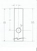
Here are some pictures of the welded in spacer.


Ken Roberts
Supporter
Here is a picture of the bolt and a link to the exact bolt.

 www.mcmaster.com

McMaster-Carr
McMaster-Carr is the complete source for your plant with over 595,000 products. 98% of products ordered ship from stock and deliver same or next day.
Last edited:
Ken Roberts
Supporter
I can measure the length of the welded spacer as well if needed. I would have already but found my micrometer battery dead...lolThanks Ken, you rock.
BTW: A friend has found your Corvette forum posts very helpful in regards to his Z06.
I have learned a lot from the Corvette Forum so I like to give back. Thank you!
Joel K
Supporter
Please do measure, I can send a battery up if needed")
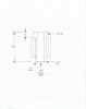
Here you go, 2.5” on mine..
Thanks Joel.
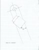
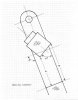
Here is what I have so far, since I have no current gen chassis to reference I appreciate the input I am getting. It appears the frame rail should be 60 degrees off the connecting "vertical" chassis beam (confirmed?). Joel, could you give some reference for the distance from the top of the vertical beam to the top side of the bellcrank rail in some fashion? Trying to confirm locale of this part vertically may be difficult to communicate.
Again, thanks in advance.
Attachments
Joel K
Supporter
Thanks Joel.
Here is what I have so far, since I have no current gen chassis to reference I appreciate the input I am getting. It appears the frame rail should be 60 degrees off the connecting "vertical" chassis beam (confirmed?). Joel, could you give some reference for the distance from the top of the vertical beam to the top side of the bellcrank rail in some fashion? Trying to confirm locale of this part vertically may be difficult to communicate.
Again, thanks in advance.
Mesa, happy to provide any measurements you need. Traveling on business today. I can take some more measurements tomorrow, just not 100% sure what measurement you are looking for.
Is the measurement you want where the green arrow is?
Howard Jones
Supporter
Joel K
Supporter
Mesa,
Here are the measurements..
Center of hole to edge of stanchion looks like 4.75”

A from your drawing above...
A is 10 9/16”
B is 11 9/16”
Keep in mind, my lower frame rails are about .25” wider than Stephan’s and Johan’s and my upper frame rail is spaced almost an inch wider than Stephan’s. So you may want to have others confirm this measurement to double check.
Here are the measurements..
Center of hole to edge of stanchion looks like 4.75”
A from your drawing above...
A is 10 9/16”
B is 11 9/16”
Keep in mind, my lower frame rails are about .25” wider than Stephan’s and Johan’s and my upper frame rail is spaced almost an inch wider than Stephan’s. So you may want to have others confirm this measurement to double check.
Last edited:
Some things you wish you never had the opportunity to know....
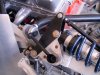
An aluminum "LSX"7 block and heads, Magnuson supercharger, connected to a Ricardo transaxle, fully dressed with AC, less headers.
765 pounds.
Engine bolted back in car, now for the tedious part of reconnecting every little thing.
20 pounds of stuff in a 10 pound bag.
An aluminum "LSX"7 block and heads, Magnuson supercharger, connected to a Ricardo transaxle, fully dressed with AC, less headers.
765 pounds.
Engine bolted back in car, now for the tedious part of reconnecting every little thing.
20 pounds of stuff in a 10 pound bag.


Similar threads
- Replies
- 14
- Views
- 2K
- Replies
- 26
- Views
- 7K
- Replies
- 5
- Views
- 785