Well done Howard....
cant wait to see some in car video and get your first impressions on the track
cant wait to see some in car video and get your first impressions on the track

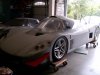
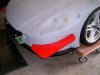
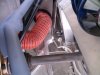
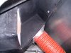
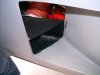
What's left? Make front canards, make diffuser/front brake cooling hose mount, make rear upright brake cooling hose mount, make duct for rear brake cooling hose, bleed brakes, bleed clutch, disassemble car for paint, transport for paint, put it all back together, Adjust everything and do alignment on car.Then I need to find a place to run it through the gears and get brake balance close. After that, fix what is wrong.
Aaron, In the back of my mind I am thinking Willow Springs in October could happen. IF I'm not living in Texas at that point.
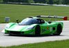
I intend to take it to Thunder Hill first available track day once I'm ready if that happens sooner.
On top of all that I need to fix my GT40 and buy another trailer, get my house ready for sale, look for a place to live in Texas while I build a house there. And move....................Busy year...............................
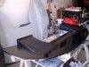
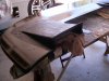
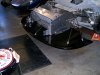
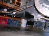
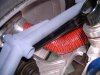
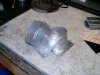
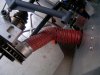
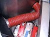
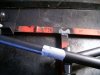
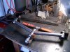
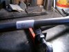
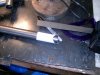
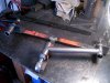
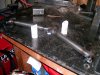
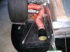
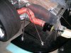
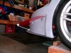
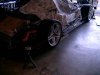
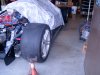
And I got to try the tubing notching program. It works and does give you a good place to start grinding. The second arm took about 2 hours to do complete with welding. I added the gussets after I took these pictures. You can see them on the brake pics.