SLC 24 Howard Jones

I just gave you what we use on the race car
But we also use 3/4 on the clutch for the porsche transaxles , even though others gave you a different option

The settings we use in the race car are for much wider slicks than you are using, they have a much taller sidewall too.

Start with -1 deg front and -0.75 rear and check your tire temps after running a hard track session
 

Howard Jones

Supporter
Here's the trig calculator I use for doing camber setting. All you need is a carpenters square, bubble level, and a 5 inch steel ruler.

Right Triangle Trig Calculator

So the fronts for example. Side B=18", Angle X=1.0, Then Side A must be .31". Just to finish the idea the rears would be 19", 0.75 and, 0.25"

B is the wheel diameter, X is the desired camber angle, and A is the distance from the vertical edge of the carpenters square to the wheel edge when the horizontal edge of the carpenters square is level to the ground. Really simple and it makes sense. You just need to be carful with you measurements.

This will get you + or - .2 degrees at 1/16 inch accuracy. If you use a very careful eye you can get this to .1 degree @ 1/32 inch accuracy.

Old people like me driving at about 95% on a good day can't really discern any better than that if we are being truthful with ourselves. It's like tire pressure changes of less that 1 pound. Not gonna happen.
 
Last edited:

Howard Jones

Supporter
So today was a sort of big day. On one hand I put the last part on the car. Car is complete as far as assembly is concerned. Then I took off each of the ball joints and checked the taper against a known correct GM part. They all seamed to be the correct 10 degree taper.

The one thing that is strange is the old castle nut fits a 18mm wrench best but also goes onto a 1/2/-24 BJ stud. I could not discern any difference between the old castle nut that came on the car and the new GM piece as far as fit. I even torqued then both to 70ftlb and they both fit just fine. In the end I used a 1/2-24 G8 nut and then put the castle nut on top to line up the carter pin hole. This seams like a good result. The only question is the origin of the BJ. I couldn't find the numbers on it associated with any of the 20 or so cross referenced BJ manufactures.

Anyway here's how to tighten the ball joints without taking off the upright or the BJ block. The picture is the fronts. Take out the hub assembly and there's plenty of room for a socket . The rears won't fit a socket but can be torqued with a crows foot. Remove the brake rotor to make it easy on yourself.

Here's a few pics of the complete car. Now Just a few thing to make work, like getting it out of the driveway. I couldn't do it. I'll need to go get some plywood latter.
 

Attachments

  • HPIM2149.jpg
    HPIM2149.jpg
    185 KB · Views: 370
  • HPIM2150.jpg
    HPIM2150.jpg
    168.5 KB · Views: 361
  • HPIM2151.jpg
    HPIM2151.jpg
    163.8 KB · Views: 431
  • HPIM2152.jpg
    HPIM2152.jpg
    180.6 KB · Views: 436
  • HPIM2153.jpg
    HPIM2153.jpg
    161.7 KB · Views: 377

Howard Jones

Supporter
I working through a "punch" list of things that need addressing. So far I have corrected a miswire in the rear lights, miswire in the turn light switch, oil temp sender location, some loose nuts and bolts in the shifter system along with re making the bell crank on the cross gate cable.

The shifter seams like butter now. Damn near perfect feeling at rest going thorough the gears. The clutch is working right and the shifter working well really takes lot of pressure off my stomach. It's funny how nervous I am about the end of the build phase. It's now or never for things that seamed like they would work when I dreamed them up. Pretty damn cool that they seam to work now.

So I still need to bleed the brakes again and figure out if I like the master piston sizes. Brakes seams a bit weak but that could be a lot of things. Then I may need to raise ride height another 1/2 - 3/4 inch just to drive it around. It is very low now at 4 inchs front and 4.5 rear.

Lastly the entire rear wing mount and diffuser/rear body mount will need to be re though. It isn't going to work if I need to take off the rear body every time I want to get to the engine room.

Today I may go get some plywood and try and clear the driveway again.
 

Howard Jones

Supporter
I agree Eric. Right now I am trying to reach a point where everything works well, then I'll take it to the track and try and get it to balance mechanically. Then on to a new discipline for me Aero balance.

This is going to take a bit longer.
 

Howard Jones

Supporter
Plywood project complete. Can now get out onto the street. Went around block at 10-15 mph. Shifts very good 1-4-R. Clutch good. Problem with brakes. I think front MC stuck in bore or balance bar issue. Brakes feel like rears only. No big deal. One thing at a time I guess.

Next drive Video.
 

Howard Jones

Supporter
Pretty sure front master was stuck in bore. Probably has been that way for a while. Those parts sat on the shelf for 6 years before they got fluid in them. They are not really meant to sit dry like that. Those of you who are reading this should bleed the brakes right away in your build process. Even if this means that you re-bleed them every year or two during your build.

By the way if I had done a bench bleed of the masters as it should be done I would have found this right away. LESSION LEARNED!!!!

For now I will do a complete re- bleed tomorrow just to get the car rolling around. Then once I have settled on MC sizes I intend to rebuild both front and rear MC 's before I go to the track.
 
A big day here in the Commie State :)
We have proof of life on another SLC.

I availed myself and recorded the proceedings (a breakfast run), as Comrade Jones woke the unwashed masses by firing up the new girl at O' sleepy-thirty this morning.

Everything went smoothly as no parts made by a certain Italian were observed bounding down the road by the chase vehicle.

Upon arrival the "devushka" did not fail to impress the peasants.


Phase One Complete
Congratulations Howard!
Thanks for sharing the journey.
 

Attachments

  • 20150718_070825.jpg
    20150718_070825.jpg
    194.4 KB · Views: 498
  • 20150718_070829.jpg
    20150718_070829.jpg
    301.2 KB · Views: 457
  • 20150718_085007.jpg
    20150718_085007.jpg
    229.5 KB · Views: 464
  • 20150718_085041.jpg
    20150718_085041.jpg
    332.1 KB · Views: 411
A big day here in the Commie State :)
We have proof of life on another SLC.

I availed myself and recorded the proceedings (a breakfast run), as Comrade Jones woke the unwashed masses by firing up the new girl at O' sleepy-thirty this morning.

Everything went smoothly as no parts made by a certain Italian were observed bounding down the road by the chase vehicle.

Upon arrival the "devushka" did not fail to impress the peasants.


Phase One Complete
Congratulations Howard!
Thanks for sharing the journey.

They do draw a crowd! Nice job Howard.
 

Howard Jones

Supporter
The rear engine cover, wing mount interference issue needed to be dealt with. Here's what I came up with. I reused all the tubing from the first mount, cut it up and made a fixed mount that stays on the car. Then went and bought 40 bucks worth of aluminum and remade the swing down wing mounts in the picture. They are held in place with two bolts/nuts and two pip pins.

As you can see it all works pretty good and now the wing can be swung down leaving the setting intact, the rear can be opened up, and it can all be done with one person.

I made the wing angle adjustable in 2 degree increment's from zero to 6 degrees angle of attract. 0,2,4,6.

I also removed the OEM RCR peddle set that came with the car and replaced it with a Tilton that came my way from a friend. In the process I changed the masters to two 3/4 from the two 7/8's that were installed before. Brakes are better now, more felt stopping rate, but I need to find a place to really give them a go. I'm thinking maybe I may be pretty close on calculated pressure front and rear but there's only really one way to do this and that is to drive the car. One known issue is new rotors and pads and no place to really bed them in or get it all hot. So I'm going with calculated numbers and feel. Not the best way to do this but that's what it is.

When I 'm done with the brakes I'll post all the piston sizes etc.
 

Attachments

  • HPIM2155.jpg
    HPIM2155.jpg
    145.8 KB · Views: 334
  • HPIM2156.jpg
    HPIM2156.jpg
    121.7 KB · Views: 272
  • HPIM2157.jpg
    HPIM2157.jpg
    163.3 KB · Views: 265
  • HPIM2158.jpg
    HPIM2158.jpg
    179.4 KB · Views: 284
  • HPIM2159.jpg
    HPIM2159.jpg
    130.3 KB · Views: 309
  • HPIM2160.jpg
    HPIM2160.jpg
    191.6 KB · Views: 315
Last edited:

Howard Jones

Supporter
I did a couple of things since my last post. First I noticed that the cockpit got really hot very quickly. I drove the car at about 6:45 in the morning fro about 15 min to coffee with some hot rod buddies. It was pretty cool and still the interior got pretty hot right away. Water temp was still below 190F and I was surprised with the cockpit temp.

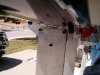
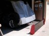
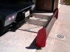
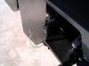
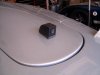
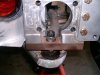
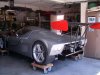
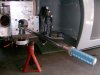
Tool the nose off when I got home and discovered that the gap between the front of the body and the chassis box is about 1/2 inch. That's where the heat was coming from. Mt radiator duct was pumping the full heat load right into the cockpit. Easy fix to seal the gap up and I made a shield to direct the radiator exhaust more efficiently out of the nose and keep the hot air off the bodywork under the front windshield.

This seams to have worked pretty well.

Second was to install a rear view camera. Here's the pieces;

[ame]http://www.amazon.com/Boyo-VTE100-Square-Eggshell-Housing/dp/B0036DEDLK[/ame]

[ame]http://www.amazon.com/Esky-Color-Video-Monitor-Remote/dp/B00T2HDGIA[/ame]


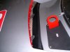
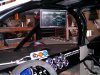
The cables that comes with these are all you need to do the install and it worked the first time I plugged it all together. The monitor mount is pretty much plastic junk but all the monitors I looked at use the same basic thing. So made my own. Simple steel bracket attached to the top center roll bar down tube bolt. Very stiff and doesn't bounce around. It's located in the same spot as a rear view mirror would be and it's a good spot because it's the darkest place in the cockpit. To much glare on the dashboard.

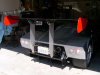
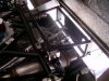
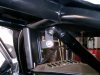
The camera is a 150 degree CCD type that most people on line think is better technology than the CMOS type. The angle is just right as far as I can tell. It comes with a cool steel mount/housing that saved me from making yet another part. I tried it all over the top of the are and this is where I liked the view to the rear the best. This location also is easy to mount the camera and run the cables back to the monitor from. Right down the rear engine room bulkhead through the conduit in the side pod to the cockpit and up under the dashboard.

It's all wired up to come on when turning on the ignition system. 12V+ to on side of ign on switch. Basically on all the time the car is running.

A lot of online opinion says to go with a good camera and save on the monitor, just use a big one so I bought a 7 inch that is fine in the spot I have it. It seams to do what I want, fill the need for a rear view mirror, and the system isn't much money really.

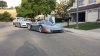
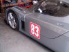
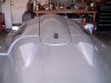
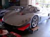
Oh I have numbers on the car. Raceline Digital made them for me. 10 bucks each, you can't beat that! They are the soap and water squeegee on kind. Really easy to do and they an be taken off with a little hot water and soap the way they went on.

RACELINE DIGITAL, Hull and Deck Graphics | Motorsport Graphics

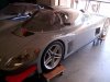
First pic is radiator duct shield, the rest are the camera install, monitor, and numbers. All that's left to do is get the seat covers altered and keep diving it to work out kinks. I'm gonna start California registration next week.

Cheers!
 

Attachments

  • HPIM2164.jpg
    HPIM2164.jpg
    157 KB · Views: 295
  • HPIM2162.jpg
    HPIM2162.jpg
    116.3 KB · Views: 277
  • HPIM2163.jpg
    HPIM2163.jpg
    196.2 KB · Views: 343
  • HPIM2165.jpg
    HPIM2165.jpg
    164.1 KB · Views: 324
  • HPIM2166.jpg
    HPIM2166.jpg
    136.9 KB · Views: 270
  • HPIM2167.jpg
    HPIM2167.jpg
    161.5 KB · Views: 274
  • HPIM2161.jpg
    HPIM2161.jpg
    128.4 KB · Views: 272
Last edited:
Looking nice Howard. Need to get over and see it in person...

Pics never do justice. Just can't see all the little details.

:thumbsup:
 

Jim Craik

Lifetime Supporter
She looks great Howie, what a beauty!

I we should get together before you leave CA...
 
Last edited:

Howard Jones

Supporter
Jim, I'm pretty sure I'll be here until next year. We are just finishing up building plans, next bid from builder, build loan, permits, HOA review. Gonna be a few weeks still before we start digging.

Love to see ya, I'm gonna do a SB100 on it I think. Maybe when that's done If I can come up with some street tires I'll meet up with ya some where. Must be flat route no drivesways with gutters or speed bumps.

You're always welcome to drop by.
 

Howard Jones

Supporter
Spent the last two days messing with the carb. The cam in this car is jus about the most extreme cam Comp cams makes for a Hyd Roller motor. So as I was fine tuning the idle screws I was having a hard time because there is very little manifold vacuum at 900 RPMs . Some where in the range of 5-10 inches of mercury. But the idle screws would make no difference.

Thank god for the internet. Huge amount of info on Holley type carbs. It turns out that if you try and use the primary idle screw to increase idle speed too much you uncover the transfer slot too much. This causes the idle mixture screws to become unresponsive. The fix is to use the secondary idle screw to add AF to the engine and back off the primary side until the transfer slot is nearly covered. The transfer slot should be square and no more as viewed from the bottom of the carb with it off the motor. You should set it and forget it and then use the secondary's to set idle.

On Holley's the secondary idle screw can be seen on the bottom face plate near one of the secondary throttle blades with the carb off the manifold. My carb. is a Proform R 750 so it has the add on secondary external idle screw mod. With this the secondary idle can be set with the carb on the engine and running. Other wise its a remove the carb trial and error deal.

Once I figured that out, the idle came up and I can now at least get some idle mixture adjustment. The idle screws change manifold vac as they should but there is still very little vac. at 800 RPMs. At 1000 things smooth out a bit and that's where I left it.

That's a lot of cam baby!
 
Back
Top