SLC 24 Howard Jones

Roger Reid

Supporter
Howard, I agree with you that setting the rear upright at vertical (at ride height) is correct. I believe it was designed that way. Howard you know all this stuff but just because this is an interesting subject...
The SLC rear double A arm suspension toe in is set by adjusting the length of the toe link. The washers above and below the outer toe link set the bump steer. Set the outer toe link too low and during suspension compression the wheel will move towards toe out (bump steer). Set the outer toe link too high and the wheel will move to toe in during suspension compression (bump steer). Set it just right and bump steer is minimized. I believe current thought is that if bump steer cannot be completely dialed out, it is better to move towards toe in than toe out. I believe this is because toe in during bump or rather roll will cause the wheel to resist rear oversteer. If the outboard rear wheel in roll went to toe out it would encourage oversteer. When the rear caster at ride height is set to zero or vertical it would only stay at zero if the two A arms were parallel. They are not. Other things that come into play are anti squat and anti dive.

Fred Puhn in his book was referring to trailing link radius rods. If the radius rods caused the wheel to move rearward during roll or bump that would induce toe out or oversteer. The opposite would cause toe in or understeer.

One thing Fred mentions in his book is to keep a log of setups and record your results. If you make a change to the worse, you can always go back.

The more you read about suspension setups you realize how much you really don’t know. Admittedly I don’t know Jack. But I do know he has a wife named Loda and two kids named Fulla and Bull.

Now if rear bump steer has been dialed out and the rear kingpin angle is zero there must be 8 plus inches of scrub radius... does rear caster really exist?
 

Howard Jones

Supporter
Rodger, that's exactly what I did when I first put the rear of the car together those many years ago. I set the upper and lower a-arms in the center of their range with an equal number of washers on each side of the rod ends. This is what Fran told me was the default setup.

I then took the spring off the shock on one side and jacked the tire up and down and measured toe. About 2 1/2 inches of bump and 1 of droop at the outside of the rim to the ground.

I keep adding and subtracting washers to move the toe link around until I found the least amount of toe change. I believe I got it to nearly nothing (toe change).

Then I set toe to 1/16" in (each side) and rechecked it again. The rear never went "toe out" so I have been using this setting every since.

It's pretty important to prevent toe out under bump especially because the loaded side in a turn is in effect in max compression and with a fully loaded tire (bump). The other side (droop) isn't doing much. Especially if the car has a significant amount of roll in it at center corner max load. If the loaded side goes toe out at that point you will see snap oversteer that can be very hard to catch. If you can keep them both at a stable toe setting then that would be the goal. The SLC is pretty good in this respect.

I think I agree that "rear caster" may not be a recognized term because in theory, the rear doesn't have a steering function and the upright doesn't pivot but everybody knows what you are referring to so that's what I use to describe rear top to bottom upright pickup point angle. Or something like that.

This kind of chassis setup from ride height blocks including a similar front bump steer check should be one of the first things to do. It will help get the a arms and suspension parts on the car in the correct location early on in the build.
 
Last edited:

Howard Jones

Supporter
You gotta have one of these. Wrestling with a gearbox is a pain in the ass, especially when you get a little...........experienced and don't have any help. NOT NOW BABY!!!!! Goes right on so easy you would call it fun!

I made it with some leftovers but something similar could be done without a welder by bolting things together or even making it out of wood. DO it now and make your life with a transaxle easy!!!!!
 

Attachments

  • HPIM2504.JPG
    HPIM2504.JPG
    937.5 KB · Views: 365
  • HPIM2505.JPG
    HPIM2505.JPG
    917.2 KB · Views: 353
  • HPIM2507.JPG
    HPIM2507.JPG
    1,001.1 KB · Views: 309
  • HPIM2506.JPG
    HPIM2506.JPG
    957.1 KB · Views: 293
  • HPIM2508.JPG
    HPIM2508.JPG
    968.9 KB · Views: 310
Last edited:

Howard Jones

Supporter
Took the car back to COTA a week or so ago, so here's a report and a video. But first an update on the winter's work and changes.

First, I have been fighting an oil leak for quite a while and I was determined to fix it for good. This time I took the engine out of the car and changed every oil-related seal in it, including the rear main and timing cover seal and all the associated gaskets including the intake manifold gaskets. The oil leak is gone. Must have been the rear main seal, because all the other ones were going on the third time.

The engine builder asked me to enlarge the breathers hoses on the valve covers so I did, from AN8 to AN12. One on each cover. I also shortened up the rear anti-roll bar push rods so that the arms are being driven at near-perfect 90 degrees when the car is neutrally loaded. I also found the looseness in the shifter and corrected that with a safety-wired screw.

The brake cooling issues that I worked on last year pointed out a need for more cooling so I improved the front rotor ducting, This seems to have worked quite well.

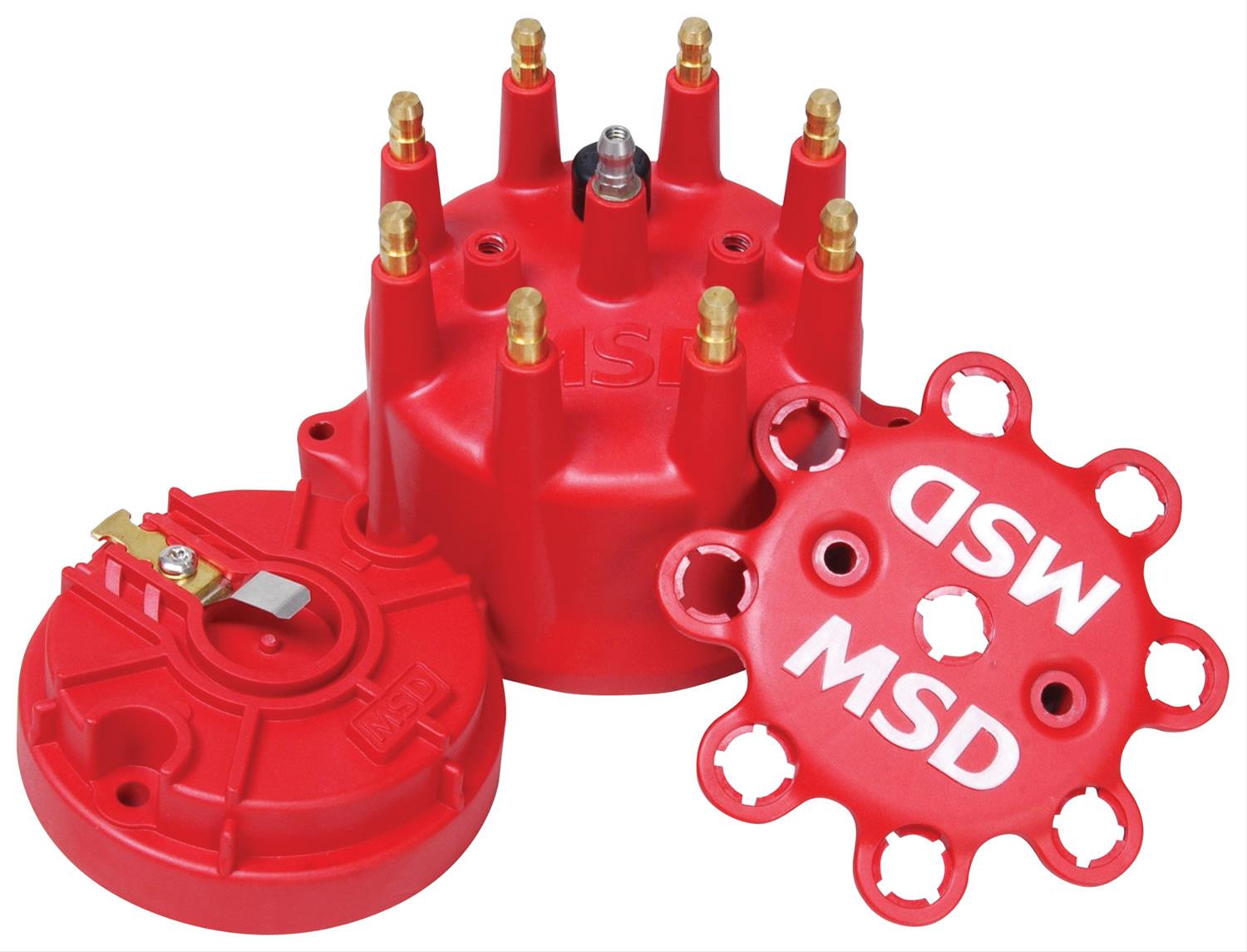
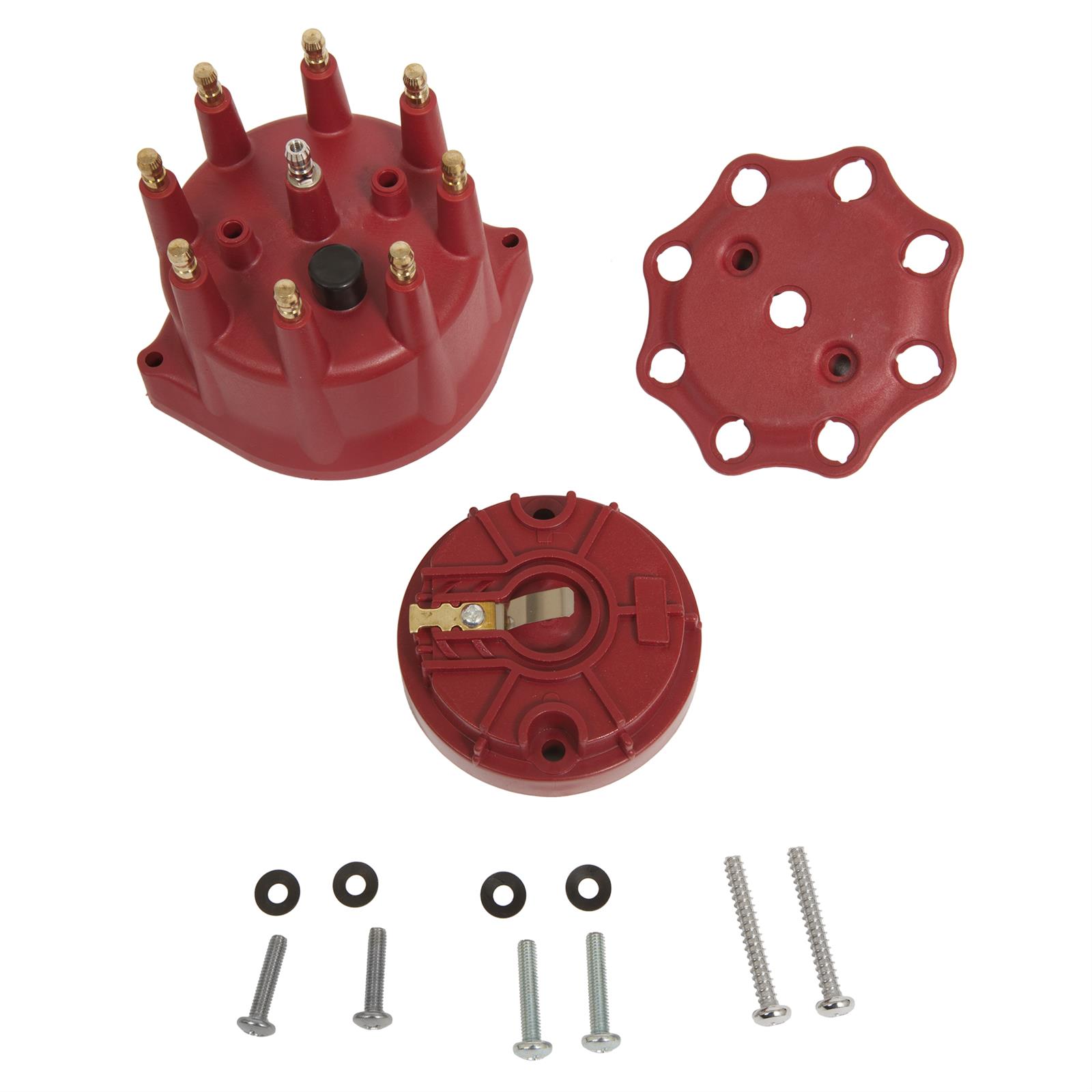
The car ran very well all day with the exception of the last session. The distributor cap failed due to excessive center button wear. The day was over so really no harm anyway.

I ran nearly the same setup as before, shocks, springs, ARB settings, and tire pressures. The day was mild with air temps in the 75 -85F range.

I am going to move up a group next time so I can get some less traffic. Here's the second session (of 5) video.


Last edited:

Randy V

Moderator-Admin
Staff member
Admin
Lifetime Supporter
Awesome stuff there Howard!
MSD or someone needs to address that center button wear issue. I’ve seen it taking numerous cars out of contention..
 

Howard Jones

Supporter
Well, it just got added to the wear item list. Change it every winter is the solution. By the way, Summit makes a replacement part that is nearly exactly the same piece for about half the price. I'll take some pictures of both parts and show ya when I get out to the shop.

Also on the to-do list is a redesign of the throttle cable routing and carb linkage in an effort to keep the cable out of the hot zones near the exhaust system.
 

Howard Jones

Supporter
So here are the pictures I promised of the MSD cap and rotor and the Summit replacement part. I'll also post Summit parts info for both below.

So I think that Summit gets the same part from whoever makes them for MSD and leaves off the MSD logos. As far as the quality goes, we'll see. However, I consider this a high-frequency replaceable part. My SLC has gone thru two caps in 2800 track miles over about 4 years. To avoid failures at events, IMHO, these parts need to changed every 1500 miles or at the 50-66% life mark. My season is typically comprised of 6, 2day, events with 12 sessions of about 25 miles per session each weekend. So if the Summit part has the same life span as the MSD part then more or less every 4th track weekend should prevent issues.

While I was at it, I decided to inspect the fuel filter. I did find some aluminum particles that I believe are from the original assembly of the car. This goes to prove no matter how much you clean the fuel system it is really never free of debris until a few hundred gallons of fuel have been pumped through it so as to filter out all the tiny little specs of swarf. I will add this filter to the annual maintenance cycle. The last couple of pictures are of the removable fuel pump assembly and the aforementioned filter.


Attachments

  • HPIM2509.JPG
    HPIM2509.JPG
    730.5 KB · Views: 227
  • HPIM2510.JPG
    HPIM2510.JPG
    714 KB · Views: 211
  • HPIM2512.JPG
    HPIM2512.JPG
    598.5 KB · Views: 198
  • HPIM2513.JPG
    HPIM2513.JPG
    593 KB · Views: 230
  • HPIM2515.JPG
    HPIM2515.JPG
    1.1 MB · Views: 218
  • HPIM2514.JPG
    HPIM2514.JPG
    668.8 KB · Views: 293
Last edited:

Howard Jones

Supporter
So I had mentioned on another thread, radiators, and aero, I believe that I had some ideas about the nose of the car and a program to improve the airflow into and out of the radiator, improve coolant system efficiency, and not increase drag while adding front downforce.

I did another 1-day event at COTA today and I believe that the first of two significant changes to the nose have made a marked improvement. I started the day with the same setup as last time. I actually believe I could feel a change in balance with the front of the car getting quite a bit more pointy and after the first session added 1 degree of rear wing. In the second session, with the added degree of AOA on the rear wing feeling so much better I added another for the third. During the third session, I believe I ran two or three laps in a row that were much quicker than I had ever gone there before. The car now has 8 degrees of AOA on the rear wing and it's staying there.

I should say here that the track group Edge Adicts have been very good to me and my strange car. Everybody whats to know what it is. Last time I was at COTA with them I was sure they would move me up to a faster run group. There was just too much speed differential, especially at the end of the two long straights. This time I got an email when I signed up and I was informed I was going to run with the next faster run group. Things went much better this time and in the third session, I was getting three to four laps in a row alone without needing to pass anyone. Even when I need to wave someone by it was much easier because neither of us really needed to change our pace much. Just a light second or two lift as they came alongside and we would continue on at our own pace. When I made a pass it was much smoother because both cars were nearer the same pace Really much better. I was stressed at first but I am really looking forward to the next time I run COTA with them.

As far as pace goes I believe I was running mid 2:30s without really any drama. This car will run as fast as a GT3 Porsche as long as the driver is on par with my ability. They have about the same power so the straights really don't make much difference and the braking on both cars is about even given slicks on both. I did have a look at one Porsche I thought was not as quick as my SLC and discovered that it was on 200 treadwear street tire. Hoosiers, even used ones, make a huge difference.

So the following pictures are what I did to the nose. I was looking at the computer models that were done on the nose of the car elsewhere and it was clear that the modeling incorporated quite a bit of difference than is standard on an SLC. At the nose radiator inlet as the car comes from RCR there is quite a large return at the top. What I am talking about is the void area up under the inside of the inlet. It is almost 2 inches to the top inside of the fiberglass. This is not optimal. So I filled it in and it seems to have made quite a difference.

If you look at the airflow model you can clearly see what would happen if the air flowing into the nose inlet lost contact with the roof of the "duct". I believe this caused a lot of turbulence right where it would do the most damage. Filling this and continuing the "duct" profile right to the radiator face is what I believe I have done and it seems to have worked.

I also reworked the exit duct that I had made previously. Instead of a step at the last 1/3 of the exit duct where I had used this change in profile to easily secure it to the chassis, I cut it out and remade this area so that it was smooth and remained straight all the way out of the duct. This was another attempt to keep airflow attached and reduce turbulence in the ducting on both sides of the radiator. Again it seems to have helped. I also noticed that I could run the car harder and quicker than ever and it seemed to run cooler. I check the oil pressure and water temp twice a lap on both straights and the water was solid 190F. This is the programed water temp target for the Davis Craig pump controller. I will admit that it was pretty mild today with ambient air temps at around 75 -85F. We will see if this holds when I run on a 95F day.

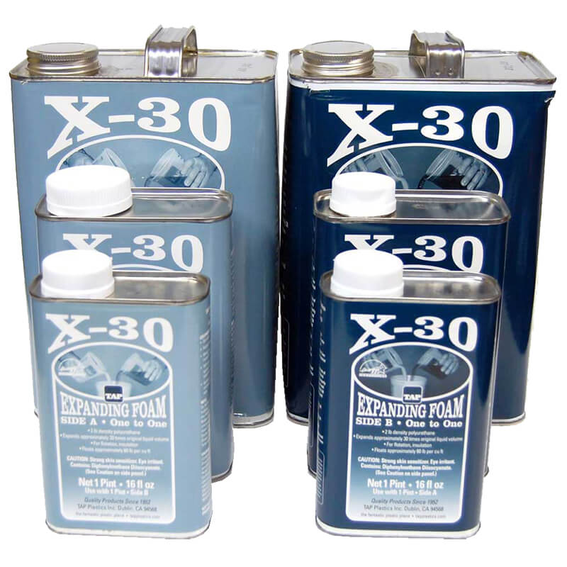
The pictures show the filled material first. This is the two-part void filling foam used on boats. If you do this, buy your foam from Aircraft Spruce. The stuff I used wasn't as good as the Aircraft Spruce stuff I used before and was just not as consistent when it expanded with some rather large bubbles that I had to mix another batch and refill after cutting them out. I then covered the foam with fiberglass cloth and painted it with primer.
 

Attachments

  • 1617897360246.png
    1617897360246.png
    306.2 KB · Views: 253
  • HPIM2516.JPG
    HPIM2516.JPG
    824.9 KB · Views: 235
  • HPIM2517.JPG
    HPIM2517.JPG
    841 KB · Views: 237
  • HPIM2518.JPG
    HPIM2518.JPG
    811.4 KB · Views: 251
  • HPIM2519.JPG
    HPIM2519.JPG
    742.7 KB · Views: 261
  • HPIM2520.JPG
    HPIM2520.JPG
    736.8 KB · Views: 243
  • HPIM2521.JPG
    HPIM2521.JPG
    803.9 KB · Views: 268
Last edited:

Joel K

Supporter
Howard, very interesting post and congratulations on getting bumped up to the next group and gaining speed and confidence in the car. Very impressive results.

Any Idea if these modification would help cooling an SL-C for street driving?
 

Howard Jones

Supporter
Filling in the area I did is very inexpensive and useful, especially while you are doing bodywork. Anything that controllers airflow through the radiator more efficiently is a good thing and better done in the build stage before you paint the car. I was going to further open up the nose next but I am going to hold off on that until I run the car on a very hot day. I think the under the nose fill-in really helped with overall cooling and just may have been enough for my car along with the exit ducting and enlarged exit hole in the top of the nose I previously did.

Vehicle speed is just one of the factors that create conditions that make these mods helpful. However, they are a sort of baseline thing to do on any high-performance car. In general radiator ducting is very important and when efficiently done might just be enough to preclude changing to expensive high flow fans. I still am using the original fans that came with the car from RCR. These mods' material costs are much less than two new fans. My guess is less than a 100 bucks.

Here's the foam. You can also get fiberglass mat and resin from Aircraft Spruce. A few yards of the mat and a quart of resin are plenty. 3 or 4 is enough but it's cheap and good to have around so get a few more than you need if you are going to make some body changes.


And other supplies:


Last edited:

Howard Jones

Supporter
I did have an issue at COTA last time that I believed was an alternator mount cracking. It was not my mount that I made but the alternator itself. Here's what I found when I took things apart. I think that using an adjustable tension arm made from two L/R rod ends and a length of tubing may have allowed the alternation to try and move when under high G loading. (Curbing the car at high speed in the esses.) This may have transferred the load to the case of the alternator in a twisting motion.

I have made a traditional tension adjustment piece out of heavy steel with a slot in it and a simple hole at the other end. This way the two ends are captured in both X and Y axises, unlike a rod end that only is fixed on one axis.

Running a car at the track hard really is so much different than using it as a streetcar The good news is this took a lot of time to fail (years) and it seems that I am finally beginning to see a much longer time to failure for the problems I do have. Things just fail that you would never believe would because the loads are so much higher and sustained for so much longer.

The last picture is the original mount system.

I guess this is why they are called prototypes!!!!!!
 

Attachments

  • HPIM2522.JPG
    HPIM2522.JPG
    808.3 KB · Views: 231
  • HPIM2523.JPG
    HPIM2523.JPG
    756.8 KB · Views: 223
  • HPIM2524.JPG
    HPIM2524.JPG
    778.4 KB · Views: 235
  • HPIM2441.JPG
    HPIM2441.JPG
    858.7 KB · Views: 213
Last edited:

Howard Jones

Supporter
Went back to COTA yesterday. It was HOT 90F at 11am and almost 100 in the afternoon. I am absolutely sure the nose contour filling in works extremely well. My car would have been running 200-210ish without it. This was with a programmed target water temp set to 191F on the controller. Manageable but worrying, with my eye always on the temp gauge, run the fans on the cooldown lap and in the paddock, open the back up right away as soon as I got out of the car etc. I was even considering adding another pump up at the radiator and cutting the radiator outlet out more.

Don't need to do any of that!

The car was ROCK SOLID at 190F on the water temp gauge and on the controller readout ALL DAY LONG!!!!!! This is a simple thing to do. Buy some foam and do it!
 

Howard Jones

Supporter
Streetcar guys. Don't take the above as the only cure for effective cooling. But a complete ducting system is a very big part of the solution. My average speed on the lap at COTA must be north of 80mph with full power for at least a 1/3 of the lap. I am running low to mid 2:30s. That is a totally different environment than 80 mph down the freeway at 10% throttle.

I am convinced that 500hp can be cooled with one Davies Craig EPW150 controlled with their controller. What would be interesting would be to put the original radiator back in and see if it would work now. That is really too much work for an experiment but if you are in the process of building a track car with around 500-550hp try what I have done to the rest of the car's ducting and bodywork and see if the RCR OEM radiator will work for you before spending a $1000 on a custom race piece.

Next up, ducting for the oil cooler.
 
Might want to consider opening up the rear clam (slotted vents) where the window used to be in order to exhaust heat better (?)
 

Howard Jones

Supporter
Of course, you are right. But if I can continue working on airflow through the car and avoiding disturbing laminar flow on the bottom and the top of the car without adding holes or more scoops, I can improve downforce. I would like to be able to cover the entire bottom of the car and run no scoops on the top but I don't think that is attainable. The main reason I did this car was to play with a car that would lend itself to the development of aero. So far I can run the car and the coolant is stable at my designed temp. Now I am going to address the oil cooler air throughflow through the car.

It seems that I am getting suficiante air into the engine room at speed with the scoops on the rear engine cover to prevent vapor lock and overheating the engine components since I insulated some of the fuel lines. I do need to open the rear of the car up after leaving the track each time but that is really a pretty simple process.

I am going to reroute the throttle cable this winter as well as possibly add a cooling duct and hose to cool the fuel pump assembly and alternator area. I also have some ideas on the front downforce that I would like to give a try. So far I can overpower the nose with the rear wing at will. The car can clearly add downforce but not without improving the front first. At present, I can get the car to aero understeer at about a 100 and aero compress at the rear at about 150 in a straight line. Since I only see 150 at COTA and then only for about 2 seconds it's not a problem. What would happen in a 150 mph corner I have no idea but I suspect that more rear spring would be required as well as the aforementioned lack of front downforce.

So if I need to add vent holes in the rear engine cover I would like to do that over the winter because I am going to repaint the nose at that time and I can do it all at one time.

We'll see but I think you are probably correct. My car is a pretty easy thing to cool because it never goes slower than 50-60 mph. A streetcar would certainly need to vent the engine cover unless you live in Alaska.
 
If you feel that you have attached airflow on your engine cover, NACA ducts shouldn't affect your aerodynamics much at all.
 

Howard Jones

Supporter
This was my thinking on NASA versus scoops.

If in fact the airflow across the top of the car is somewhat attached to begin with on the windscreen, with the practical form of the car roofline being what it is, detached flow is inevitable. Especially the sharp transition at the roof/windshield. After that working rearward, there are way too many nuts, bolts, windshield clamps, body gaps, door henges, mirrors, and the big ass scoop on the roof, etc. Airflow must be somewhat turbulent and detached by the time it reaches the edge of the rear clip.

So I decided that a NASA duct in the same location as my scoops wouldn't work whereas a scoop would. If you study NASA ducts, you will see very quickly that attached airflow at the entrance to the duct is VERY important. If it is turbulent at that point then very little air will flow into the duct,
 
Back
Top