Howard Jones
Supporter

Ken, I am suggesting using dowels to rigidly locate the adapter plate in place so that the hub is firmly located on the upright by its center indexing shoulder. Then the clamping force is provided by the three other hub mounting bolts that go all the way through the upright, adapter plate, and then fasten to the hub itself.
I don't propose bolting the hub to the adapter and then the adapter and hub as a sub assembly to the upright. This is possible due to the uniform outboard surface of the upright on the gen 1 version....
That's interesting. So the adapter becomes a spacer. That's fantastic as long as the inboard side of the upright has flat areas to accommodate the 3 bolt heads...
I would skip the C6 X Tracker hub and go right to a C7 hub instead due to how much cheaper they are as long as you can get a 33 spline stub shaft to fit and play nice with your existing axles.
I think you have a great idea. I'd say re-drill the upright for the new C7 hub bolt pattern (by re-clocking the new hub) and make a spacer, for the outboard side, the correct thickness from 6061 aluminum.
The only challenge will be to have a 33 spline stub shaft made the correct length to play nice with the existing axles. I guess a custom spacer could be used there as well if an existing stub shaft was in the market place but was a bit shorter...
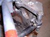
On our second Gen rear uprights (like mine shown in this picture) it's too bad we couldn't just machine the stock protruding flange flat and get a special billet adapter created to take up the difference in depth and bolt pattern of the C7 hub. . My Pen is pointing to the protruding flange that could be machined off. You could supply us with a special adapter and new design 33 spline axle stub shaft. We could then take our uprights to a local machine shop to have the existing protrusion removed.
Ken, thank you for that. I was not aware that there are two versions of the sculpted gen2-3 upright. See, you are being very helpful!