
You are using an out of date browser. It may not display this or other websites correctly.
You should upgrade or use an alternative browser.
You should upgrade or use an alternative browser.
SPF p2348
- Thread starter jammin man
- Start date
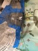
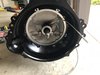
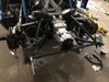
Took nearly a year to get the transaxle from RBT. Seems sacrilegious to cut into it but here goes:
Will need to take the bell housing off and mount it to the transaxle to bevel the bottom edge a little more
Will need to take the bell housing off and mount it to the transaxle to bevel the bottom edge a little more
Attachments
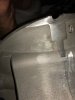
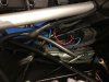
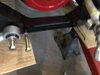
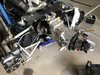
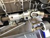
Was planning to hook up the oil pressure (which is mechanical) but the fitting I have is 1/4NPT. Searching on the web it looks like the Boss 302 block has a 1/2 NPT at the left front (although the 2nd pic shows another spot you can use on the back right that is 1/4NPT). I prefer the front position as it's further from the headers. Do you think I could find a 1/2NPT mechanical oil pressure fitting? Noooooo. Looks like it's 1/2 male NPT to 1/4 female NPT adapter time. Don't know what I'd do without Amazon Prime.
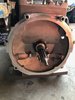
First pic is left front and the mount jutting out on the left is where the dry sump pump mounts (where a mechanical fuel pump would go.
First pic is left front and the mount jutting out on the left is where the dry sump pump mounts (where a mechanical fuel pump would go.
Attachments

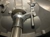
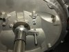
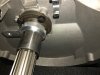
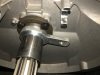
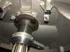
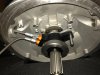
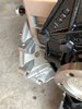
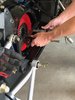
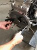
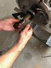
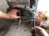
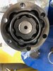
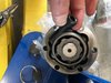
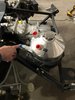
Nothing is easy with this car. Lot's of stops and starts. Was in NC for my 2 niece's graduation and stopped up to pic up this aluminum fitting to mount the throwout bearing. Took me a few days to realize something was missing. Called Dennis and his guys fabricated one. He showed me how it fit and I get home and it doesn't fit. (the pics below are with the transaxle upside down for reference) The olive colored base plate to the input shaft must be different. It has a bevel on it's face and the fitting I have doesn't. No problem, I could have a friend who's a great fabricator do that but the cutouts for the screws (to keep the piece from spinning) don't match up to the screw position on the base plate. I'm not sure how important that is because once the throwout bearing is on you can see it really doesn't want to go anywhere. When fully seated, it only spins the distance between pic 4 and 5. The 2 lines on the throwout will also keep it from spinning much as well. Will be checking with Dennis to see what he thinks. I can probably have my friend do that as well. Can't really figure out the shims until it's set though. More delays...
Will bring the bleed line out a drill hole in the flare as Dennis does
Will bring the bleed line out a drill hole in the flare as Dennis does
Attachments
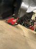
Back in the saddle. I found a fabricator closer to home so the aluminum fitting has been modified and now seats fully and interdigitates with the screws so it won't spin. Dennis recommended cutting a hole in the flare of the transaxle casing for the bleeder hose. Studs are in place on the two top threads and I ground out the holes in the bellhousing so that I can get the nuts on the threads and a box wrench over them to tighten.
Attachments

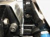
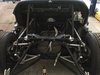
Next up, I purchased a steel bracket to reinforce the bottom of the horse collar. Not sure if this is where it goes or if it belongs between the lower control arm and the rear cage that holds the rear clam. Any thoughts are welcome!
Attachments
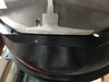
I bought that bracket several years ago. Don't remember if I ever checked to see exactly where it's supposed to go. Brilliant! OK, next question is on the throwout bearing. I've measured the distance from the bellhousing face to the fingers (first photo) and next I'm supposed to measure the distance from the bearing to the "face of the transmission". Intuitively, that would seem to be the second picture (which is where the transaxle will contact the face of the bellhousing). When I look on youtube, it looks like they're measuring to the deep face 3rd photo). The video is showing a different model release bearing though.
Attachments
Bill Kearley
Supporter
I should have taken some pictures to show the correction issues with the RBT / Kennedy with fitment in CAV. I had a machine shop mill a chunk from starter bulge and a cut across the bottom in order to have the engine as low as possible. Then weld in covers. I found it strange that Kennedy did not have their name or part number on the product. I even called them about it, and mentioned that the bell was a little to long/thick.
As for the release bearing I used about 7 shims and welded a plate and a stud to one of them that sits between the cross shaft supports to stop rotation. Fluid lines in and out using cross shaft holes.
The only other problem I had was the bearing support could have been a bit longer, at least a half inch, easy to cut of, not so to make it longer.
I got an early one off the line, hope there good. Dalynn told me he would make longer bearing supports a over year ago and after a few calls I gave up on him.
But then he has my $20000.00 Canadian, !!!!!!!!!!!!!
Bill Kearley
Supporter
What bearing do you have there Steve?
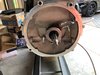
Transaxle is in. This is the proper face to measure for the throwout. Unfortunately, the throwout "wobbles" a bit with the shims. I had the aluminum fitting machined down a bit which necessitated more shims. Overall bearing clearance should be 0.100 to 0.120 inches. It will thoroughly suck if I have to take the transaxle out again anytime soon.
Attachments
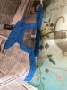
Unpacked the half shafts today and they're nearly dry. Not sure what SPF was thinking. So, will be taking them apart this week and repacking. The bolts that are included have no lock washers. I also have no torque specs, which I'm assuming means "tighten it as much as you can......but don't strip it 'ya moron". Dennis gave me a little trick to use some RTV on the bolts to minimize the tendency to loosen.
Planning on Royal Purple ultra performance grease, although open to opinions.
Planning on Royal Purple ultra performance grease, although open to opinions.
Attachments
I TORQUED MINE TO 65 FT LBS..AND USED BLUE LOK-TITE (CAV GT40)
Bill Kearley
Supporter
Just putting mine together as well, Not much room for the boot strap using those bolts.
Re: p2348
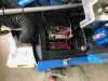
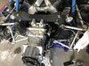
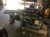
Dennis is adding a lot of goodies. The engine is from DSS racing in St. Charles, IL. Sitting in my garage. Boss 302 iron block with Dart CNC aluminum heads, shaft Jesel rockers with Ti valves and Be seats with Aviaid dry sump. Should rev to 7250-7500rpm. Compression ratio is knocked down to 10.5:1 so I can run the crappy 91 octane we have here in MN. Solid lifter roller cam is designed to work with Webers (someday?).
You will have to cut the front off to make that one fit Bob Mortimer p2340
Attachments
Similar threads
- Replies
- 45
- Views
- 3K
- Replies
- 2
- Views
- 574
- Replies
- 0
- Views
- 280